System for mounting components on boards
- Summary
- Abstract
- Description
- Claims
- Application Information
AI Technical Summary
Benefits of technology
Problems solved by technology
Method used
Image
Examples
first embodiment
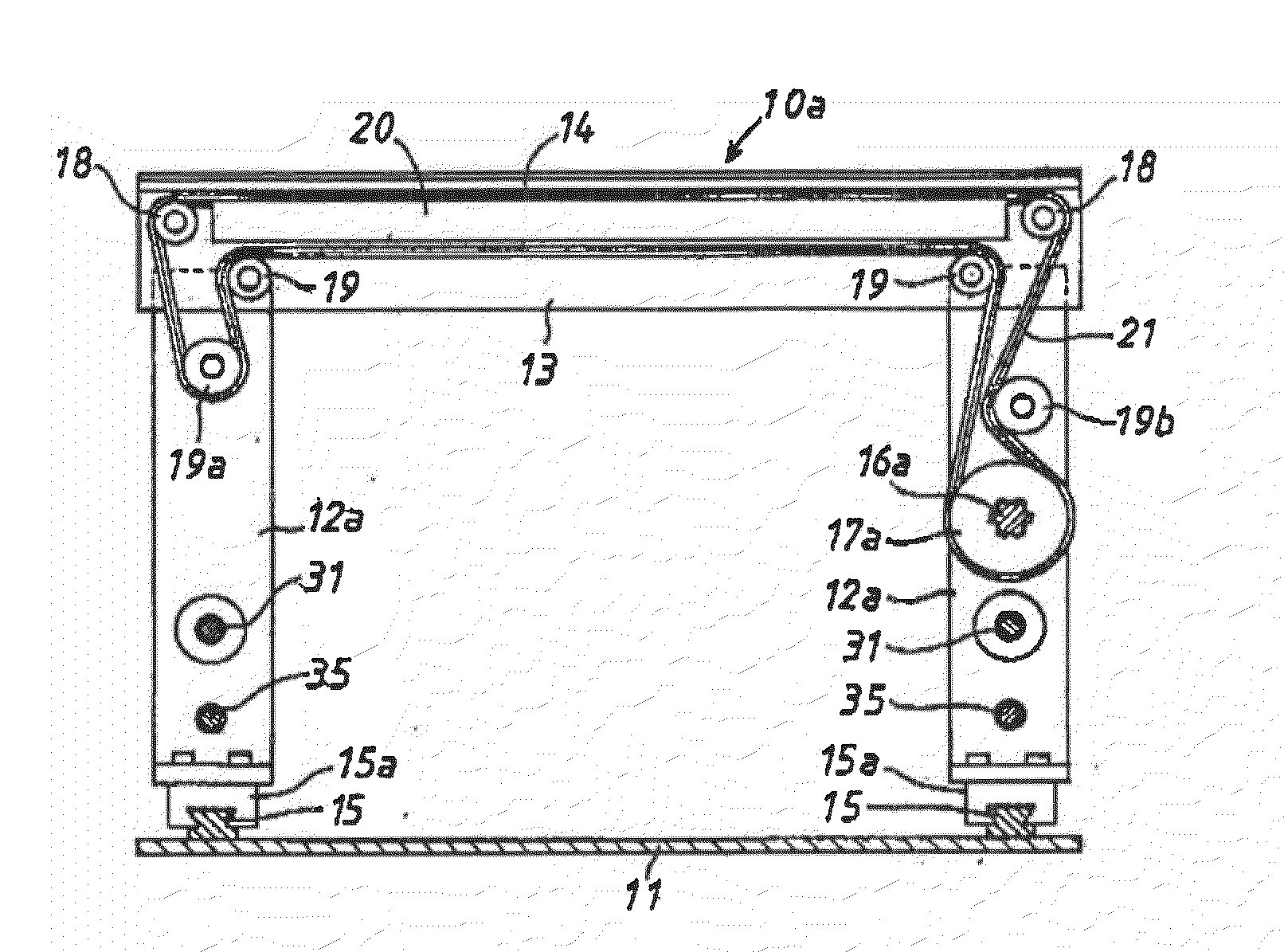
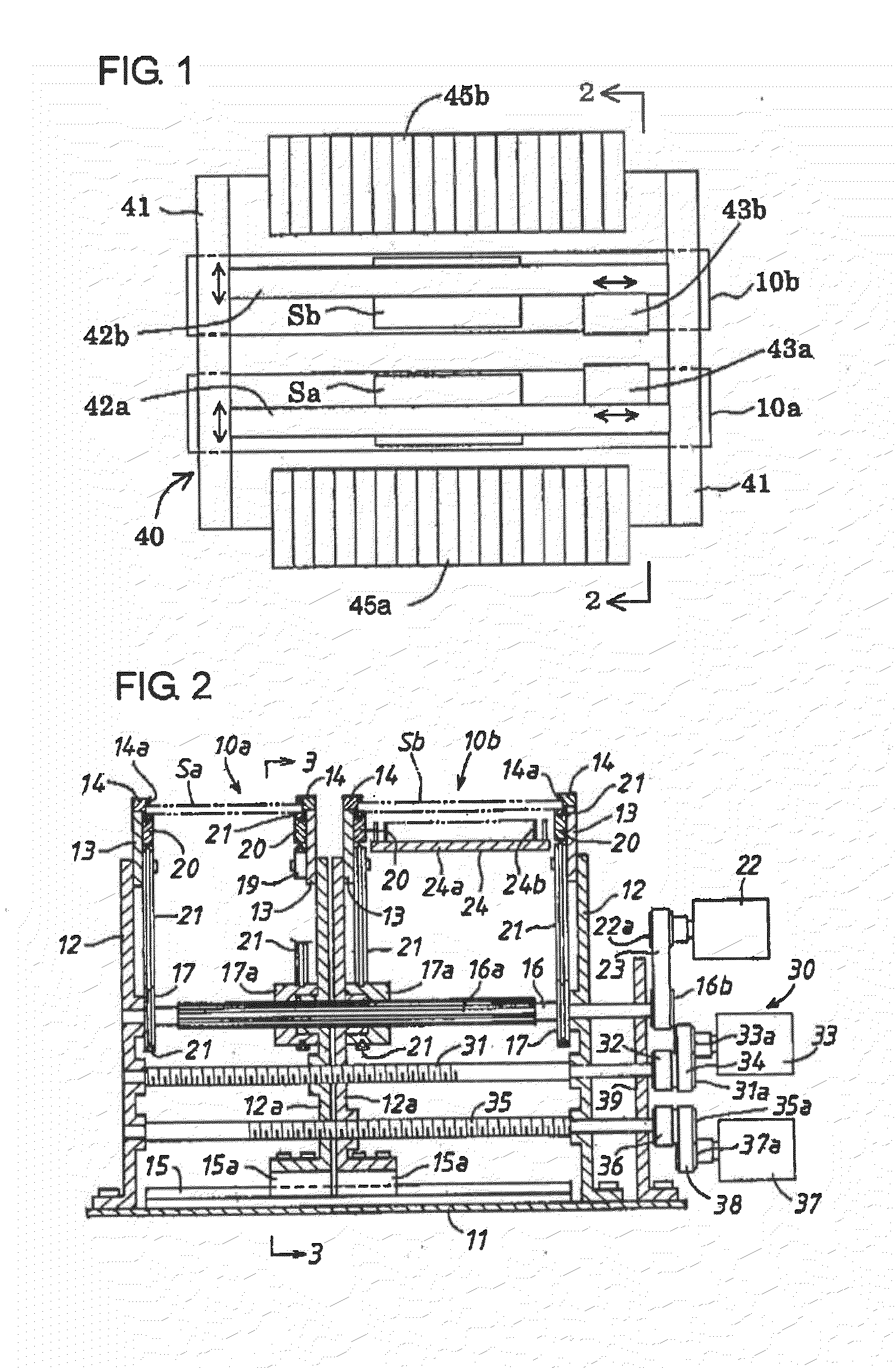
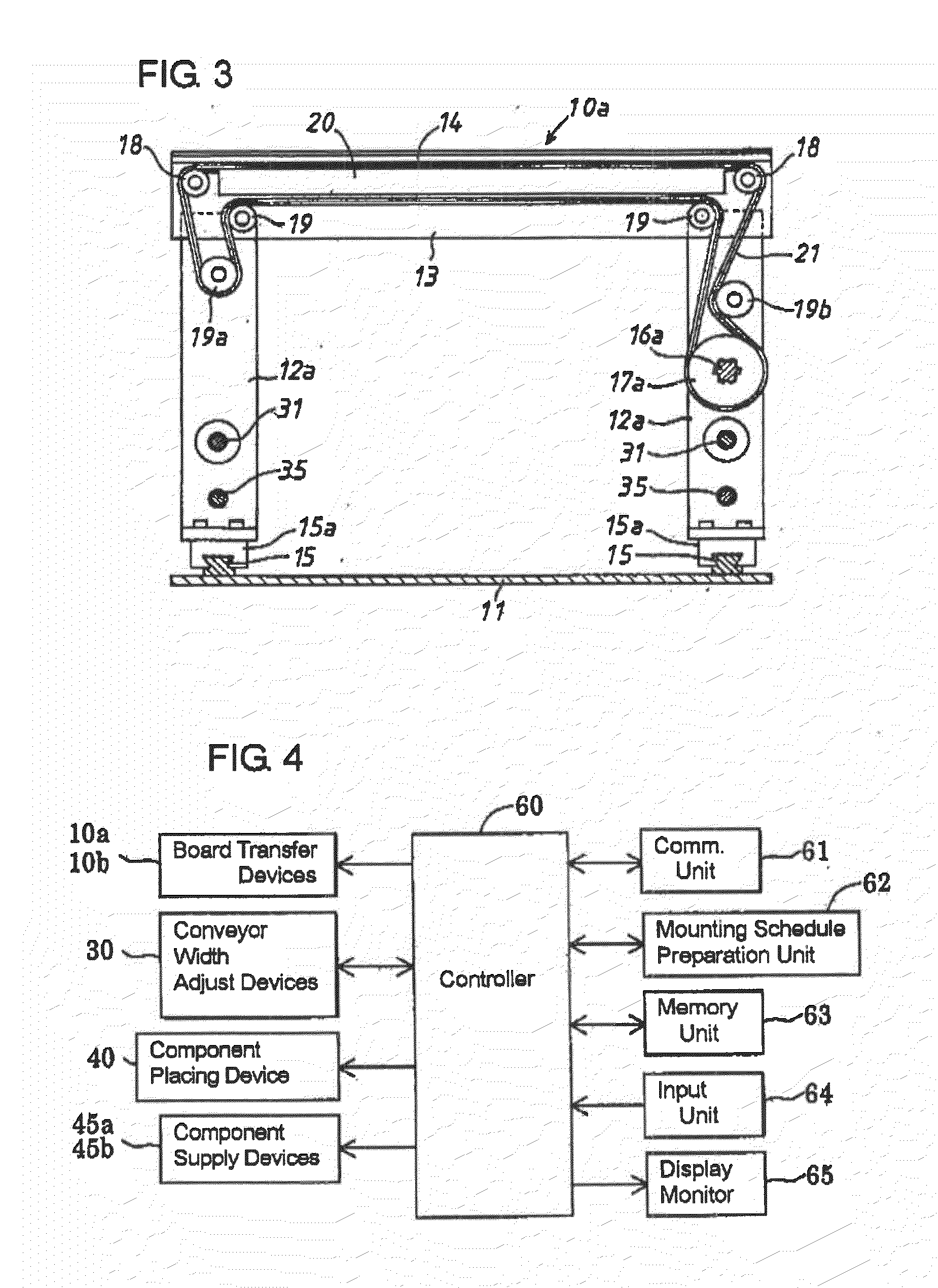
[0061]First of all, the operation of the first embodiment provided with the two board transfer devices 10a, 10b, the two component supply devices 45a, 45b and the component placing device 40 which is now assumed to have a single component placing head 43 contrary to the two illustrated placing heads 43a, 43b will be described with reference to FIGS. 5 to 7. As mentioned earlier, the component mounting apparatus in the first embodiment is operated in accordance with a mounting program which is designed to obviate the situation that the two board transfer devices 10a, 10b are both in operation to transfer the boards Sa, Sb at the same time.
[0062]The operation of the first embodiment will be described with reference to a flow chart shown in FIG. 24. When neither of the board transfer devices 10a, 10b is transferring the board Sa or Sb thereon, nor is adjusting the transfer way width thereof, the controller 60 advances the control operation from Step 100 to Step 104 by way of Steps 101 ...
second embodiment
[0070]In the second embodiment shown in FIG. 9, the two board transfer devices 10a, 10b are controlled to make different from each other the stop positions in the transfer direction to which the boards Sa, Sb are respectively stopped for component mounting operations thereon. The predetermined interference risk zones Si, Si adjacent to the central portion between the boards Sa, Sb during the component mounting operations no longer exist where the respective stop positions are separated a suitable distance or more. This advantageously can preclude the chance that the two component placing heads 43a, 43b interfere with each other in mounting components respectively on the boards Sa, Sb. Therefore, the efficiency in mounting components on the boards Sa, Sb can be enhanced, and at the same time, the program for controlling the operation of the component mounting apparatus can be simplified.
third embodiment
[0071]In the aforementioned second embodiment, the interference of the two component placing heads 43a, 43b is obviated by devising the physical arrangement of the stop positions of the boards Sa, Sb. For the same purpose or effect, the third embodiment is practiced as shown in FIGS. 10 and 25 respectively as a time chart and a flow chart, wherein by devising the control program for the component mounting apparatus, the interference can be obviated without shifting the stop positions of the boards Sa, Sb from each other. Likewise as aforementioned, on the assumption that the first component placing head 43a mounts components mainly on the board Sa while the second component placing head 43b mounts components mainly on the board Sb, this third embodiment will be described hereinafter.
[0072]At the beginning, when neither of the first and second component mounting heads 43a, 43b is mounting any component within the interference risk zone Si on the board Sa (or Sb) corresponding thereto...
PUM
| Property | Measurement | Unit |
|---|---|---|
| Width | aaaaa | aaaaa |
Abstract
Description
Claims
Application Information
 - R&D
- Intellectual Property
- Life Sciences
- Materials
- Tech Scout
- Unparalleled Data Quality
- Higher Quality Content
- 60% Fewer Hallucinations
Browse by: Latest US Patents, China's latest patents, Technical Efficacy Thesaurus, Application Domain, Technology Topic, Popular Technical Reports.
© 2025 PatSnap. All rights reserved.Legal|Privacy policy|Modern Slavery Act Transparency Statement|Sitemap|About US| Contact US: help@patsnap.com


