Cooling system

a technology of cooling system and cooling chamber, which is applied in the direction of domestic cooling apparatus, lighting and heating apparatus, battery/fuel cell control arrangement, etc., can solve the problem of increasing the power loss of the drive circuit, and achieve the effect of rapid increase in the temperature efficient and rapid heating of the power storage mechanism

Active Publication Date: 2010-03-04
TOYOTA JIDOSHA KK
View PDF2 Cites 32 Cited by
  • Summary
  • Abstract
  • Description
  • Claims
  • Application Information

AI Technical Summary

Benefits of technology

[0032]According to the above-described cooling system, it is possible to more efficiently and rapidly warm the power storage mechanism by the cooling medium that exchanges heat with the drive circuit and the electric load that generate heat.
[0033]According to the present invention, the small-sized, low-cost device configuration enables rapid increase in temperature of the power storage mechanism.

Problems solved by technology

According to the above-described cooling system, in the configuration in which the cooling system for the drive circuit also serves as the cooling system for the power storage mechanism, if an amount of heat generated from the drive circuit is insufficient for performing temperature-raising control during temperature-raising control of the power storage mechanism, a power loss of the drive circuit is increased.

Method used


Image

  • Cooling system
  • Cooling system
  • Cooling system

Examples


Embodiment Construction

[0049]An embodiment of the present invention will hereinafter be described in detail with reference to the drawings. It is noted that the same reference characters in the drawings show the same or corresponding portions.

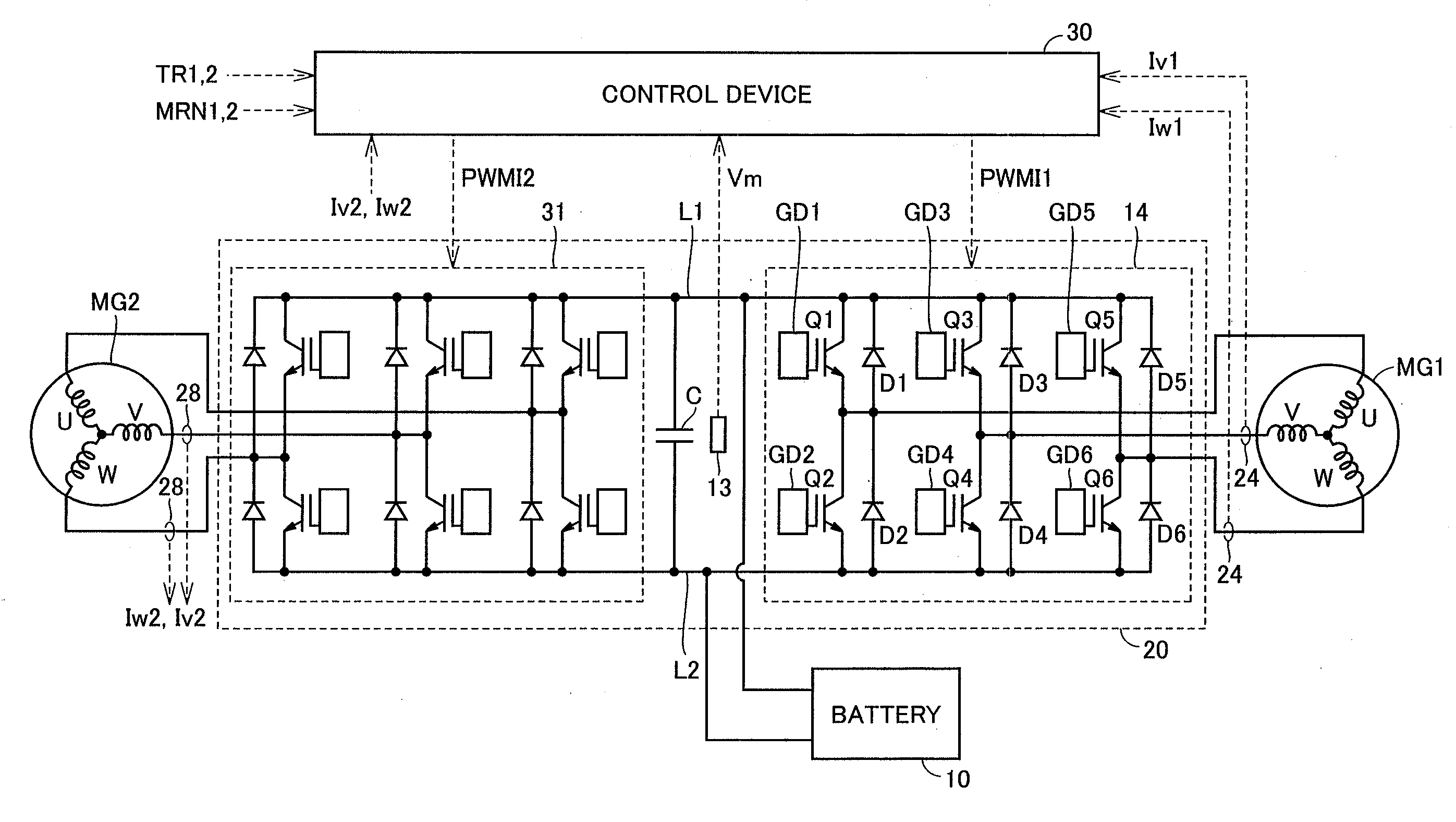
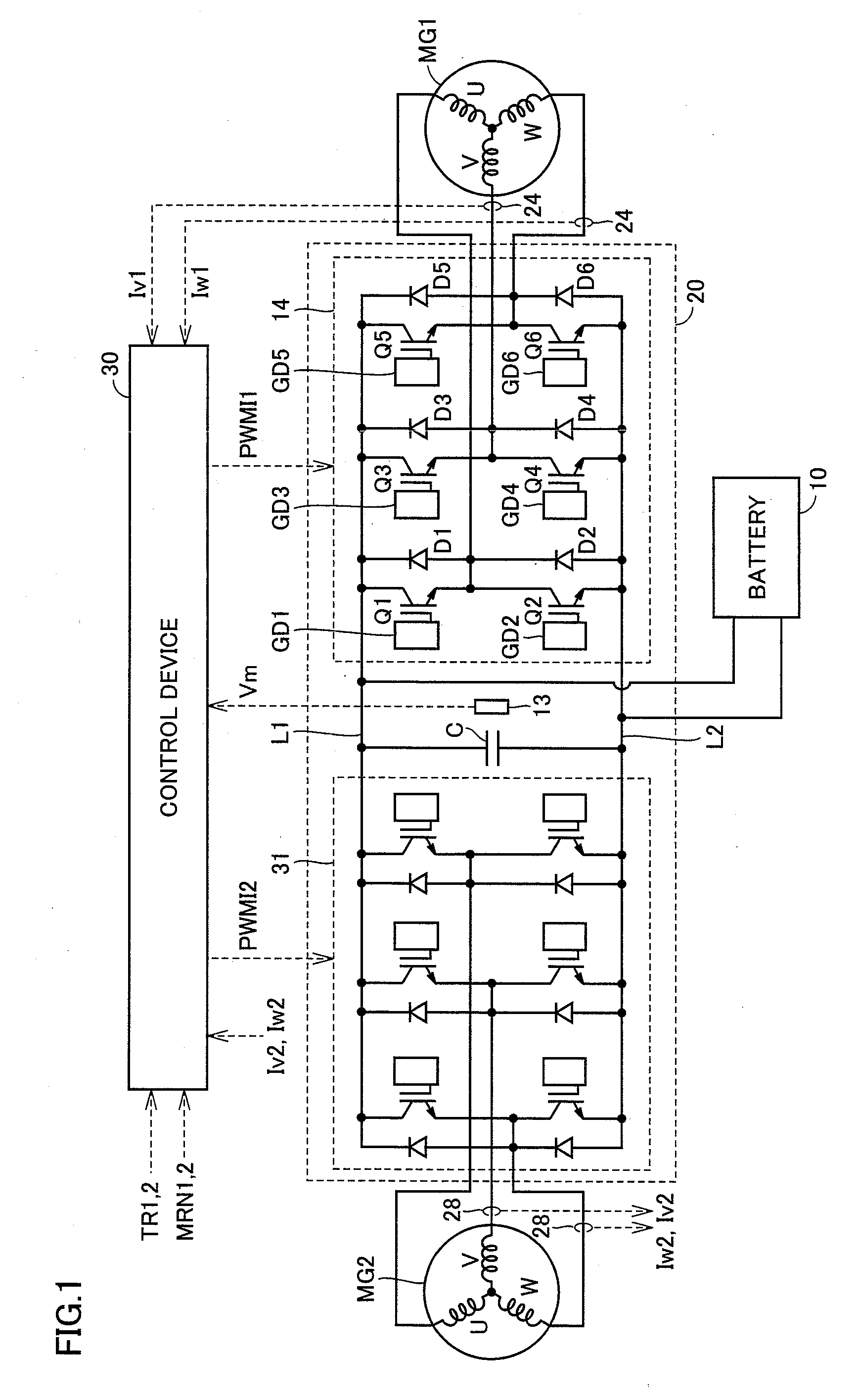
[0050]FIG. 1 is a circuit diagram for describing a configuration of a load drive device to which a cooling system according to the present invention is applied.

[0051]With reference to FIG. 1, the load drive device includes motor generators MG1, MG2, an inverter device 20, a battery 10, current sensors 24, 28, and a control device 30.

[0052]Each of motor generators MG1, MG2 is a three-phase alternating-current synchronous electric motor generator, and includes a rotor having a plurality of permanent magnets at an outer peripheral surface, and a stator around which a three-phase coil for generating a rotating magnetic field is wound. Each of motor generators MG1, MG2 operates as an electric motor that rotates and drives the rotor by an interaction between a magnetic fie...


PUM


Abstract

A cooling system has a configuration in which a cooling system for an inverter device and a motor generator also serves as a cooling system for a battery. In this configuration, a control device performs temperature-raising control of the battery when a battery temperature is below a prescribed temperature lower limit value. The control device controls an operation of a switching valve such that cooling water from a cooling medium path is outputted to a bypass path. Further, if a cooling water temperature is lower than a prescribed temperature, the control device controls the inverter device such that a power loss during a switching operation in a switching element included in the inverter device becomes larger than a power loss during normal control. As a result, the cooling system having a small-sized, low-cost configuration rapidly recovers capacity decline of the battery, which occurs at low temperatures.

Description

TECHNICAL FIELD[0001]The present invention relates to a cooling system, and particularly relates to a cooling system for a load drive circuit.BACKGROUND ART[0002]In recent years, attention has been focused on a vehicle that uses an electric motor as a drive power source, such as an electric vehicle, a hybrid vehicle, or a fuel-cell vehicle, from an environmental standpoint. Such a vehicle is mounted with a power storage mechanism made of a secondary battery or an electric double layer capacitor, for supplying electric power to the electric motor and for converting kinetic energy into electric energy and storing the same during regenerative braking.[0003]In such a vehicle that uses an electric motor as a drive power source, it is desirable to increase a charge / discharge capacity of the power storage mechanism so as to improve traveling performance such as acceleration performance or continuous traveling distance.[0004]On the other hand, the power storage mechanism utilizes an electro...

Claims


Application Information

Patent Timeline
Patent Type & Authority Applications(United States)
IPC IPC(8): F25D31/00B60K11/02B60L3/00B60L11/18
CPCB60K11/02B60L2200/26B60K2001/005B60L3/0046B60L3/0053B60L11/123B60L11/14B60L11/1872B60L11/1874Y02T10/6217Y02T10/7005Y02T10/705Y02T10/7077Y02T90/34B60K2001/003B60L50/16B60L50/61B60L58/25B60L58/26B60L58/27Y02T10/62Y02T10/70Y02T10/7072Y02T90/40
Inventor TAKAMATSU, NAOYOSHIYAMAZAKI, TAKESHI
Owner TOYOTA JIDOSHA KK
Why Eureka
Try Eureka