Infrared sensor calibration system and method

Active Publication Date: 2010-03-04
THE BOEING CO
View PDF2 Cites 12 Cited by
  • Summary
  • Abstract
  • Description
  • Claims
  • Application Information

AI Technical Summary

Benefits of technology

[0011]The above-described needs associated with IR calibration systems of the prior art are specifically addressed and alleviated by the various embodiments disclosed herein which provide a calibration system which may be implemented as a graphical software tool for

Problems solved by technology

Unfortunately, because prior art methods of calibrating IR sensor settings are performed manually, they may be subject to inaccuracies.
The result may be a poor estimation of the IR sensor settings.
Another drawback of prior art calibration methods is related to the relatively short period of time during which certain thermal imaging events occur.
Because of the short imaging

Method used


Image

  • Infrared sensor calibration system and method
  • Infrared sensor calibration system and method
  • Infrared sensor calibration system and method

Examples


Embodiment Construction

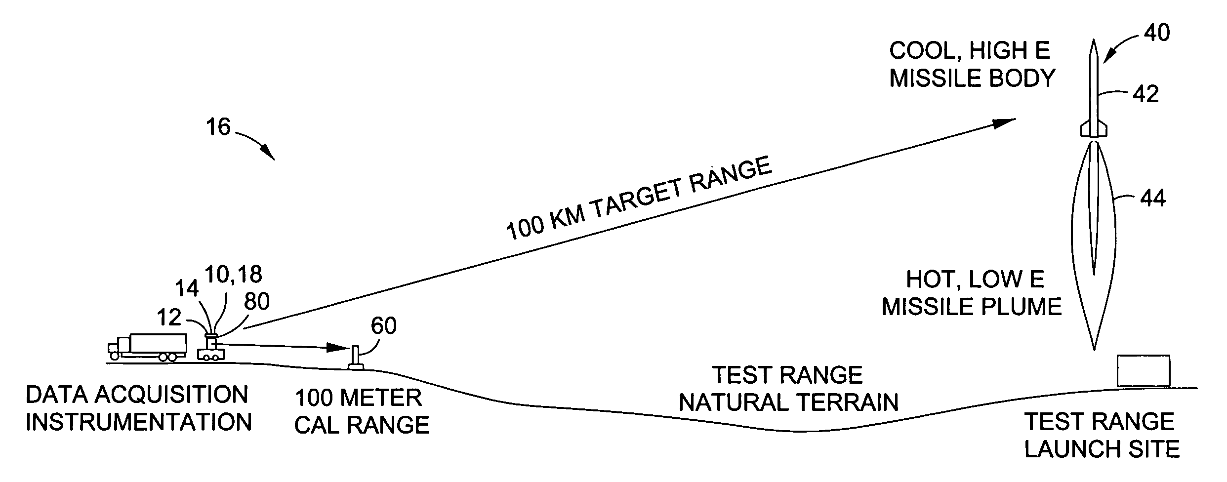
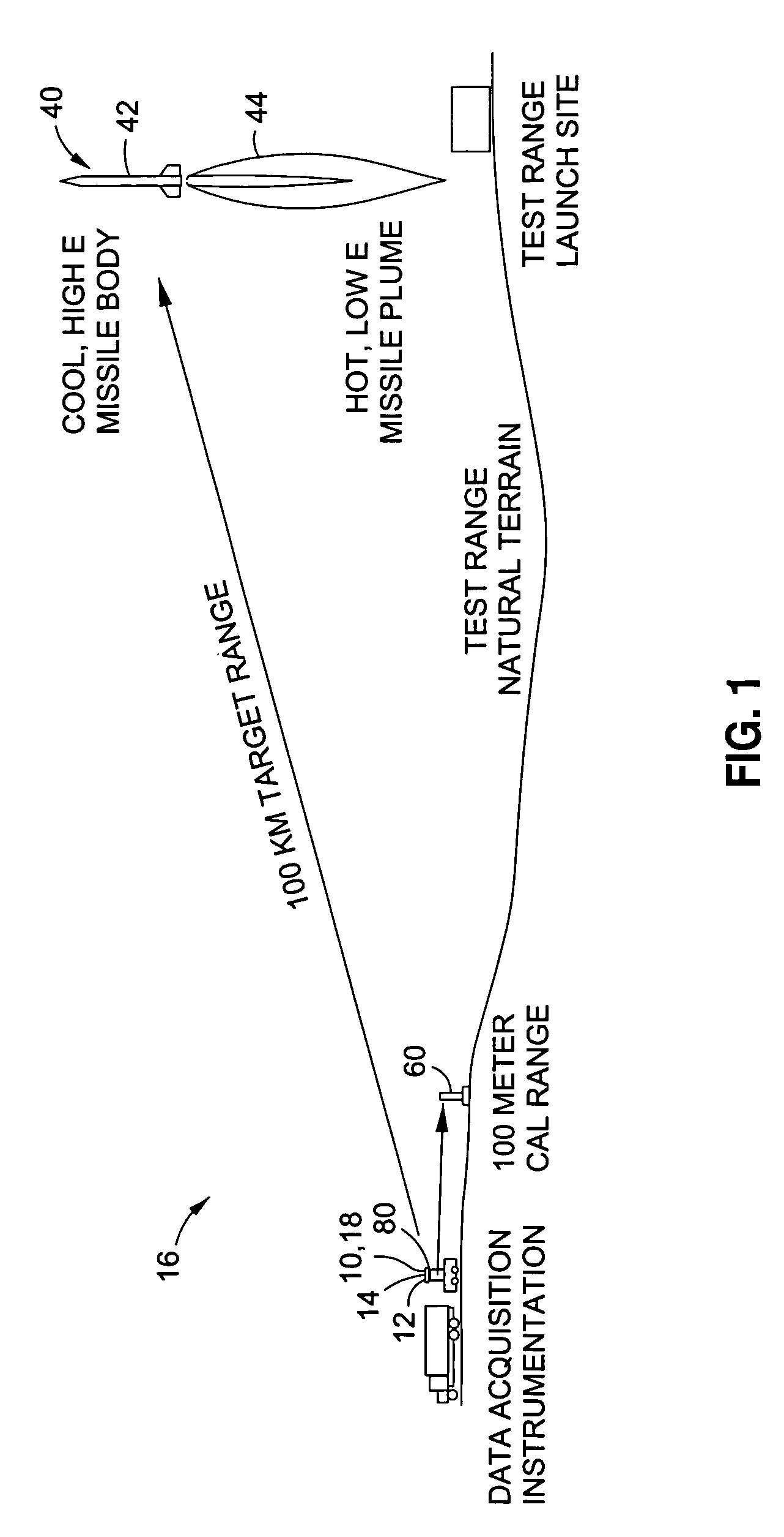
[0035]Referring now to the drawings wherein the showings are for purposes of illustrating preferred embodiments of the disclosure and not for purposes of limiting the same, shown in FIG. 1 is an illustration of an infrared imaging system 10 for imaging a long-range (e.g., 100 km) target 40 such as a missile using a calibration system 80 for close-range (e.g., 10 m) calibration of an infrared sensor 18 using at least one and, more preferably, a plurality of blackbody calibration sources 60.

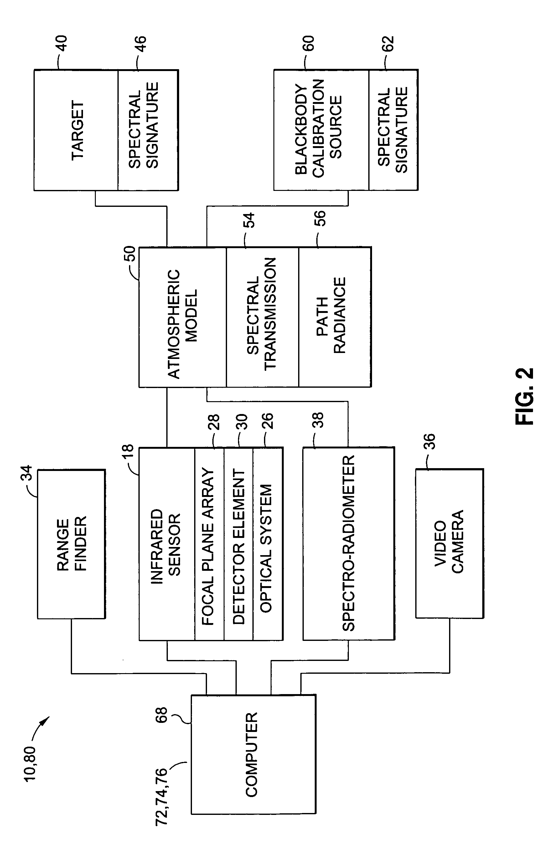
[0036]In a broad sense, the disclosed calibration system 80 is adapted to calibrate and configure at least one infrared sensor 18 (e.g., camera, spectro-radiometer) to enable setting of the infrared sensor 18 for accurate measurement of the long-range target signature. The calibration system 80 uses spectral data from a broad range of components in order to minimize the risk of saturation of the infrared sensor 18 during radiometric measurements of the target 40. Such components include, but are no...


PUM


Abstract

A calibration system for an infrared imaging system includes an infrared sensor having a sensor model for imaging a target having a target spectral signature. The infrared imaging system includes an atmospheric model having atmospheric spectral values. The calibration system comprises a blackbody calibration source having a calibration source spectral signature and a computer for receiving the sensor model, the target spectral signature, the calibration source spectral signature and the atmospheric spectral values. The computer predicts a target spectral signature propagation at the infrared sensor and matches the target spectral signature propagation with the calibration source spectral signature propagation to determine a blackbody calibration source temperature for radiometric calibration of the infrared sensor.

Description

CROSS-REFERENCE TO RELATED APPLICATIONS[0001](Not Applicable)STATEMENT RE: FEDERALLY SPONSORED RESEARCH / DEVELOPMENT[0002](Not Applicable)BACKGROUND[0003]The present invention relates generally to thermal imaging systems and, more particularly, to an infrared sensor calibration system for determining exposure settings, non-uniformity correction temperatures and calibration temperatures to use at close range for measurement of high temperature targets at long range.[0004]Infrared (IR) sensor systems are commonly used to generate thermal images of a scene being viewed. For example, IR sensor systems may be used in long-range detection and tracking of various targets including missiles and aircraft. The IR sensor produces a radiometric IR signature which generally represents the amount of infrared energy emitted by the tracked object in comparison to objects in the background.[0005]For imaging an object, it is necessary that the range of temperatures emitted by the tracked object fall w...

Claims


Application Information

Patent Timeline
IPC IPC(8): G01D18/00G01J5/02
CPCG01J5/0022G01J2005/0081G01J5/025G01J5/0275G01J5/0295G01J5/04G01J5/047G01J5/08G01J5/0846G01J5/0859G01J5/10G01J5/522G01J2005/0048G01J2005/0077G01J5/02G01J5/48G01J5/80G01J5/53
Inventor ROGERS, ELDON
Owner THE BOEING CO
Why Eureka
Try Eureka