Systems and methods for despeckling a laser light source

a laser light source and laser light technology, applied in the field of laser light source based projection television, can solve the problems of distracting viewers, and affecting the enjoyment of viewers, and achieve the effect of reducing or eliminating the recognition or awareness of screen speckling by viewers

Inactive Publication Date: 2010-03-04
MITSUBISHI ELECTRIC US
View PDF21 Cites 19 Cited by
  • Summary
  • Abstract
  • Description
  • Claims
  • Application Information

AI Technical Summary

Benefits of technology

[0007]The embodiments provided herein are directed to systems and method that eliminate or significantly reduce a viewer's recognition or awareness of screen speckling due to scintillation. In one embodiment, a television includes a video display screen mounted on an enclosure and a laser light source, an image engine, and optics including mirrors and lenses optically coupled to the display screen. Laser light from the laser light source is directed toward first and second mirrors on its way to a spatial light modulator and projection optics. Preferably the first and second mirrors are incompletely flat, and preferably one or both of the first and second mirrors move or are caused to rotate by motors. Alternatively, the first mirror or the second mirror, or both, vibrate or oscillate in the direction the light beam is traveling. Optionally, a collimating lens is included to correct the

Problems solved by technology

However, as with other systems using laser light, laser light source based PTVs can experience the occurrence of speckling as the images are projected on to the screen.
The speckling that h

Method used


Image

  • Systems and methods for despeckling a laser light source
  • Systems and methods for despeckling a laser light source
  • Systems and methods for despeckling a laser light source

Examples


Embodiment Construction

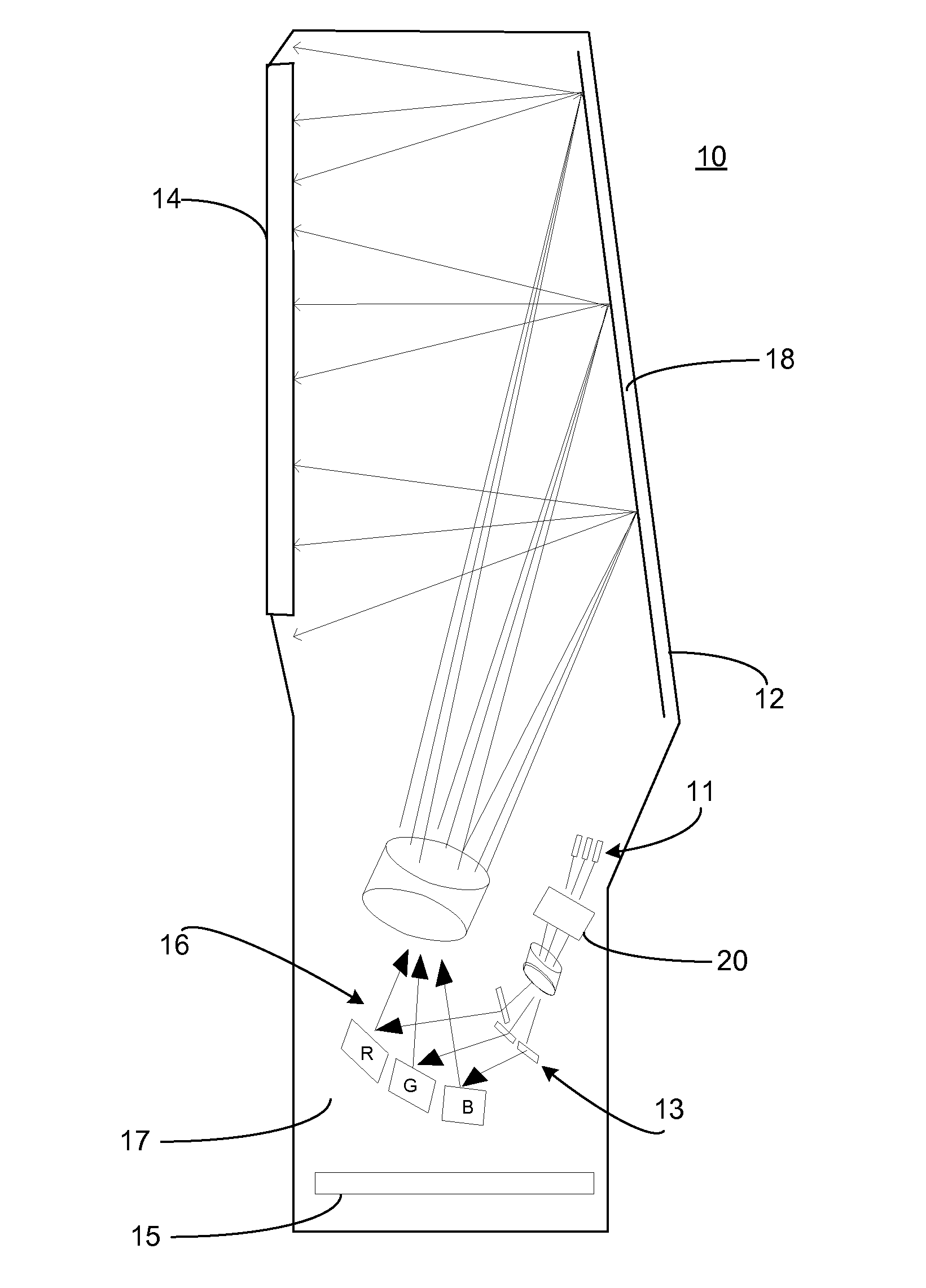
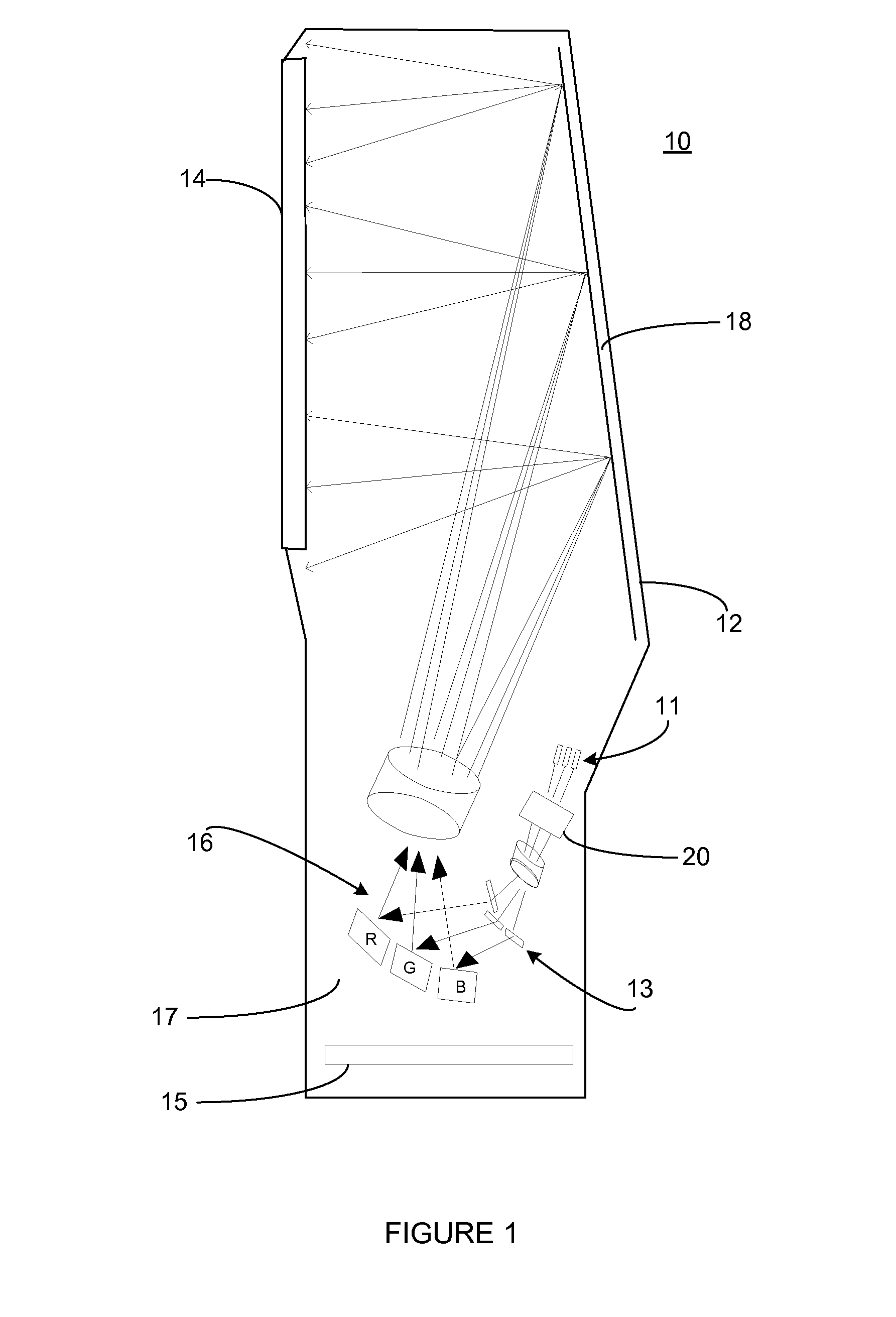
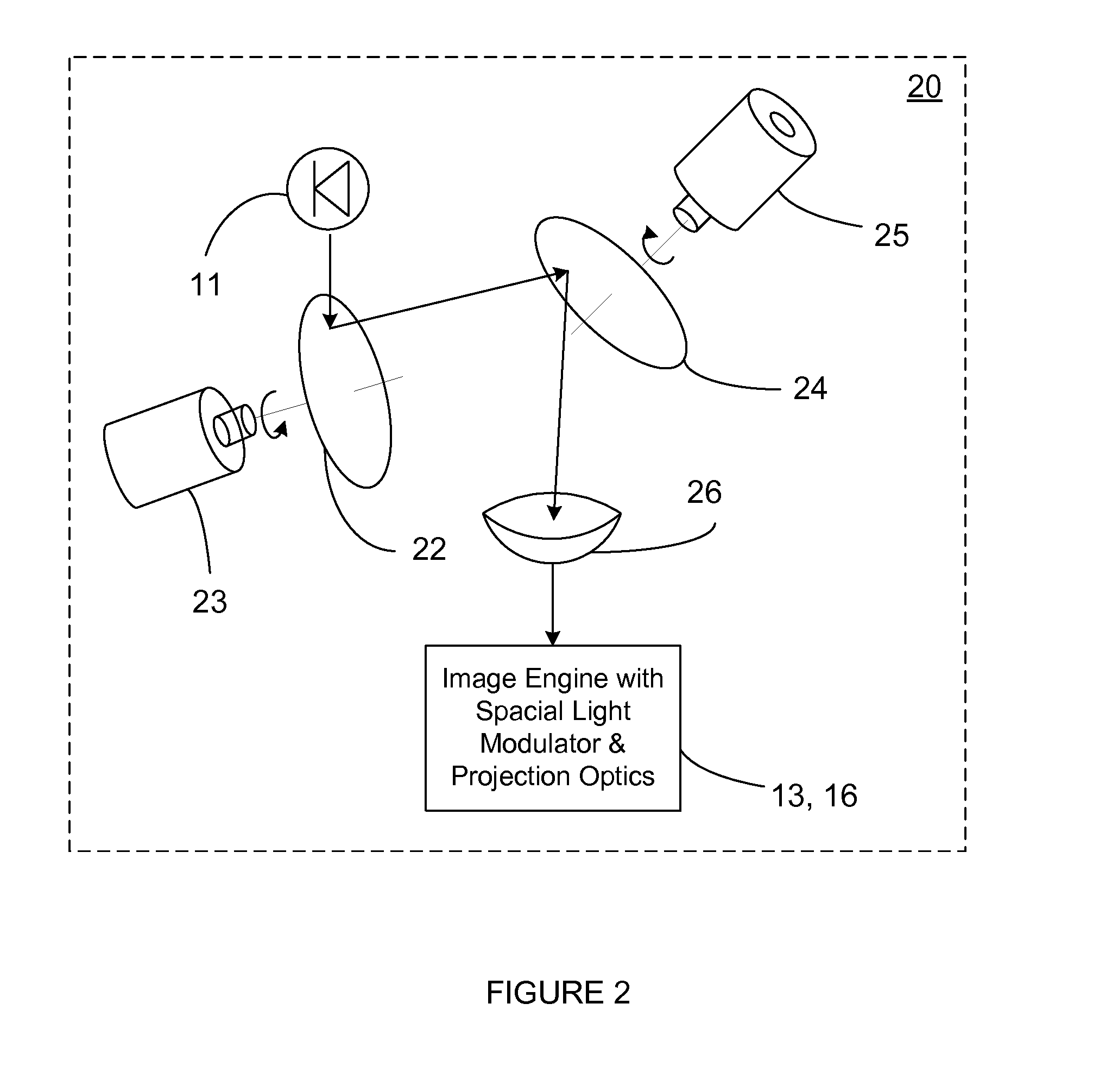
[0014]Each of the additional features and teachings disclosed below can be utilized separately or in conjunction with other features and teachings to produce systems and methods that eliminate or significantly reduce a viewer's recognition or awareness of screen speckling due to scintillation. Representative examples of the present invention, which examples utilize many of these additional features and teachings both separately and in combination, will now be described in further detail with reference to the attached drawings. This detailed description is merely intended to teach a person of skill in the art further details for practicing preferred aspects of the present teachings and is not intended to limit the scope of the invention. Therefore, combinations of features and steps disclosed in the following detail description may not be necessary to practice the invention in the broadest sense, and are instead taught merely to particularly describe representative examples of the pr...


PUM


Abstract

Systems and methods that facilitate the de-speckling of a laser source in a projection televisions. In a preferred embodiment, laser light from a laser source strikes first and second mirrors on its way to a spatial light modulator and projection optics. Preferably the mirrors are incompletely flat, and preferably move or are caused to rotate. The mirrors preferably deviate from flatness by an amount of at least one or more wavelengths, and rotate at a rate different than the video frame rate and at different rates from one another to ensure that light encountering the deviation of the first mirror strikes the second mirror at a different location than on the first mirror. As the coherent light is reflected by the mirrors the path length it takes continuously changes thereby continuously changing the phase of the light striking the screen causing the bright spots in a speckle pattern to continuously disappear and reappear elsewhere on the screen.

Description

CROSS-REFERENCE TO RELATED APPLICATION[0001]This application claims priority to provisional application Ser. No. 61 / 093,331 filed Aug. 31, 2008, which application is fully incorporated herein by reference.FIELD[0002]The embodiments described herein relate generally to laser light source based projection television and, more particularly, to systems and methods that facilitate the elimination or reduction of laser light source despeckling on a display screen.BACKGROUND INFORMATION[0003]Laser light source based projection televisions (PTVs) have a much larger color gamut than conventional projection televisions enabling images to be displayed using a greater range of colors resulting in images with brilliant colors. However, as with other systems using laser light, laser light source based PTVs can experience the occurrence of speckling as the images are projected on to the screen.[0004]The speckling that happens when an illuminating laser strikes a rough surface of the display screen...

Claims


Application Information

Patent Timeline
IPC IPC(8): H04N3/26G02B27/48G03B21/28
CPCG02B27/48G03B21/2033G03B21/208
Inventor MAXSON, BRIAN D.
Owner MITSUBISHI ELECTRIC US
Why Eureka
Try Eureka