Method of transmitting modulated signals multiplexed by frequency division multiplexing and physical quantity detector using this method

Active Publication Date: 2010-03-04
DENSO CORP
View PDF2 Cites 9 Cited by
  • Summary
  • Abstract
  • Description
  • Claims
  • Application Information

AI Technical Summary

Benefits of technology

[0021]An object of the present invention is to provide, with due consideration to the drawbacks of the conventional method of transmitting modulated signals multiplexed by frequency division multiplexing, a method of transmitting a plurality of modulated signals, obtained by modulating a plurality of carrier waves having frequencies with respective transmission signals and multiplexed to produce an input signal by frequency division multiplexing, to a synchronous detector, in which synchronou

Problems solved by technology

Therefore, the detector requires a large number of analog circuits, so that it is difficult to manufacture a small-sized detector.
Further, the analog circuits are easily influenced by external noise, so that it is difficult to reproduce the transmission signals in the detector with high precision.
Therefore, the use of the detector is limited to specific environments substantially having no external noises.
In this detector, each moving average inevitably has an error.
Therefore, when a transmission signal is superimposed onto a high frequency carrier wave, errors in the moving averages added and subtracted in the calculation corresponding to the cycle of the carrier wave are not effectively cancelled out.
In this case, the error in the voltage level of the transmission signal extracted from the input signal becomes large, so that the precision of the transmission signal extracted in th

Method used


Image

  • Method of transmitting modulated signals multiplexed by frequency division multiplexing and physical quantity detector using this method
  • Method of transmitting modulated signals multiplexed by frequency division multiplexing and physical quantity detector using this method
  • Method of transmitting modulated signals multiplexed by frequency division multiplexing and physical quantity detector using this method

Examples


Example

First Embodiment

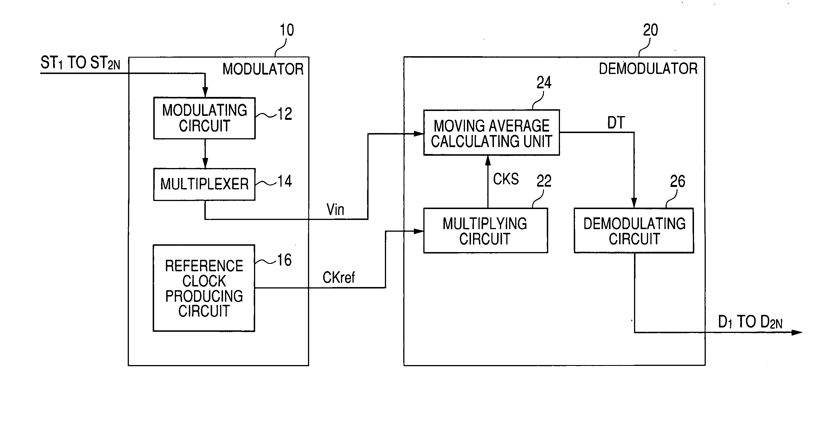
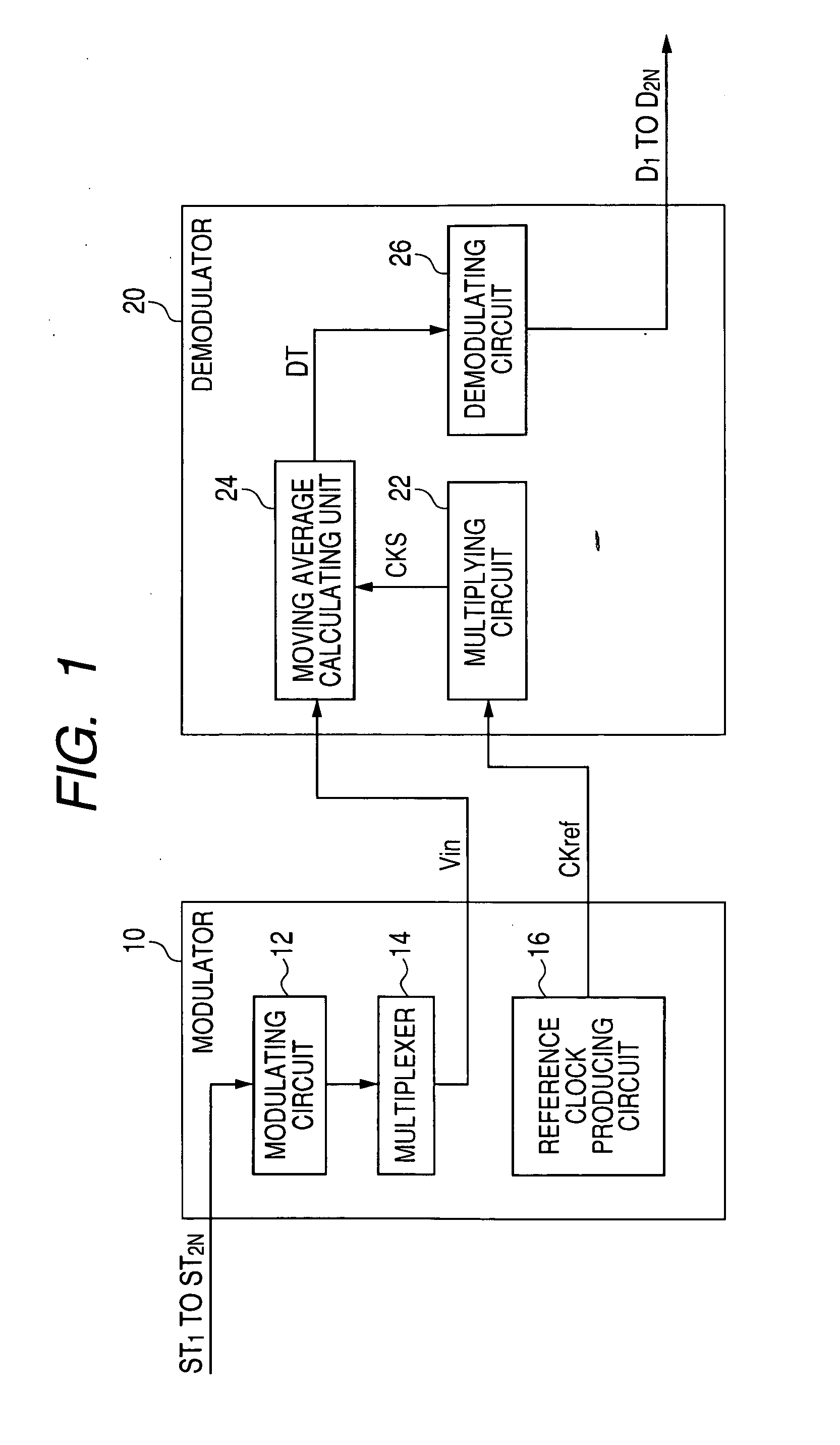
[0063]A method of transmitting a plurality of modulated signals, obtained by modulating a plurality of carrier waves having different frequencies or phases with respective transmission signals having various signal levels and multiplexed to produce an input signal by frequency division multiplexing, to a synchronous detector to reproduce or extract the transmission signals from the input signal in synchronous detection with high precision regardless of the levels of the transmission signals will be described according to the first embodiment.

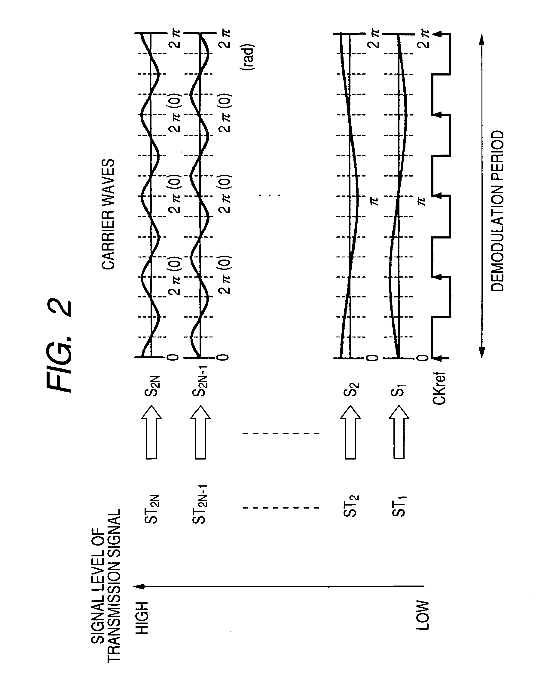
[0064]FIG. 1 is a view schematically showing a signal multiplexing and transmitting system in which a signal multiplexing and transmitting method is performed according to the first embodiment, while FIG. 2 is an explanatory view showing the carrier waves to be modulated with transmission signals in a modulating circuit of the system. FIG. 3 is a flow chart showing a signal multiplexing and transmitting method according to the fi...

Example

Second Embodiment

[0112]In the first embodiment, the reference clock signal CKref, of which the phase is synchronized with the phase of one carrier wave having the highest frequency, is transmitted to the demodulator 20 to produce the sampling signal CKS from the signal CKref and to calculate one moving average every sampling period indicated by the sampling signal CKS. In this case, the sampling signal CKS is substantially placed at its leading edge at each timing the carrier wave crosses its fluctuation center. Therefore, in the addition and subtraction calculation corresponding to each carrier wave, the difference between the sum of the moving averages in the first phase period of the carrier wave and the sum of the moving averages in the second phase period of the carrier wave is calculated as a synchronous detection result.

[0113]However, in the second embodiment, no reference clock signal CKref is transmitted to the demodulator 20. Therefore, the phase of the sampling signal CKS...

Example

Third Embodiment

[0127]A physical quantity detector for detecting a physical quantity by using the method according to the first or second embodiment will be described. In this embodiment, this detector is, for example, disposed on a vehicle to detect the strength of acceleration applied to the vehicle in the x-axial direction (or first direction), the strength of acceleration applied to the vehicle in the z-axial direction (or second direction), the strength of acceleration applied to the vehicle along the y-axial direction (or third direction), the level of angular velocity such as yaw rate applied to the vehicle around an x-axis, and the level of angular velocity applied to the vehicle around a y-axis.

[0128]FIG. 13 is a perspective side view of a sensor of a physical quantity detector according to the third embodiment.

[0129]As shown in FIG. 13, a sensor 50 has a case 45 with a cylindrical side wall 42, a top cover 43 closing the top opening of the wall 42 and a bottom cover 44 clo...


PUM


Abstract

A transmitting method has steps of modulating carrier waves having frequencies set at ½N−n (n≦N; n is a positive integer) of a reference frequency with transmission signals to produce modulated signals, multiplexing the modulated signals by frequency division multiplexing to produce an input signal, and transmitting the input signal to a synchronous detector in which the transmission signals are extracted from the input signal by calculating a moving average of the input signal every sampling period of time corresponding to the reference frequency and performing an addition and subtraction calculation corresponding to the cycle of each carrier wave for the moving averages. The frequency of each carrier wave, modulated with one transmission signal having a first signal level, is equal to or lower than the frequency of any carrier wave modulated with another transmission signal having a second signal level higher than the first signal level.

Description

CROSS-REFERENCE TO RELATED APPLICATION[0001]This application is based upon and claims the benefit of priority of the prior Japanese Patent Application 2008-226405 filed on Sep. 3, 2008, so that the contents of which are incorporated herein by reference.BACKGROUND OF THE INVENTION[0002]1. Field of the Invention[0003]The present invention relates to a method of transmitting a plurality of modulated signals, obtained by modulating a plurality of carrier waves having frequencies with respective transmission signals and multiplexed to produce an input signal by frequency division multiplexing, to a synchronous detector (or a coherent detector), in which synchronous detection is performed to extract the transmission signal, corresponding to each modulated carrier wave of the input signal, from the input signal by calculating a moving average of the input signal every sampling period of time and performing an addition and subtraction calculation, corresponding to the cycle of the correspon...

Claims


Application Information

Patent Timeline
IPC IPC(8): H04J1/00H04L27/28H04J11/00H04L27/26
CPCG01C19/00G01C19/56H04L27/2601G01P15/131G01P15/18G01P15/125
Inventor TERAZAWA, TOMOHITOWATANABE, TAKAMOTO
Owner DENSO CORP
Why Eureka
Try Eureka