Wine aerator

a technology of aerators and wine, which is applied in the direction of mixing, transportation and packaging, rotary stirring mixers, etc., can solve the problems of time-consuming transfer operation, distasteful foamed wine, and time-consuming operation, and achieves convenient portability, rapid and efficient air commingling, and the effect of increasing the effective surface area

Inactive Publication Date: 2010-03-11
CHENG PETER S
View PDF4 Cites 49 Cited by
  • Summary
  • Abstract
  • Description
  • Claims
  • Application Information

AI Technical Summary

Benefits of technology

[0008]Thus, this invention does not wait for the wine to passively interact with the atmosphere, and does not require one to manually decant the wine from the wine bottle to another container, but instead, expedites the aeration of wine in situ within the wine bottle by affirmatively forcing the wine flow and the air stream in countercurrent directions against each other, thereby achieving an intimate, rapid and efficient commingling of the air and the wine. The use of the rotating fins is particularly advantageous since they effectively scatter the wine into droplets and greatly increase the effective surface area between the air and the individual droplets. The device is readily portable and has a small footprint.

Problems solved by technology

This was a time consuming operation and needed to be performed well in advance of consumption of the wine.
Here again, this transfer operation was time consuming and required not only a separate decanter, but also a steady hand to avoid wine spillage.
However, pressurized air generated foam, and a foamed wine was distasteful.
Although generally satisfactory for its intended purpose, the gravity return was a time-consuming procedure and, in any event, the wine was not sufficiently aerated.

Method used


Image

  • Wine aerator
  • Wine aerator
  • Wine aerator

Examples


Embodiment Construction

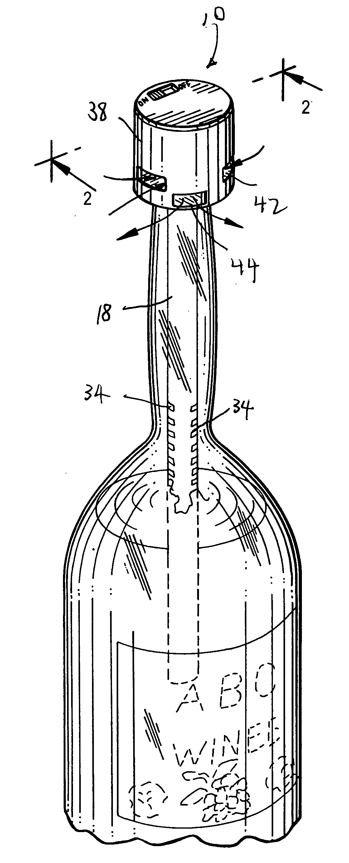
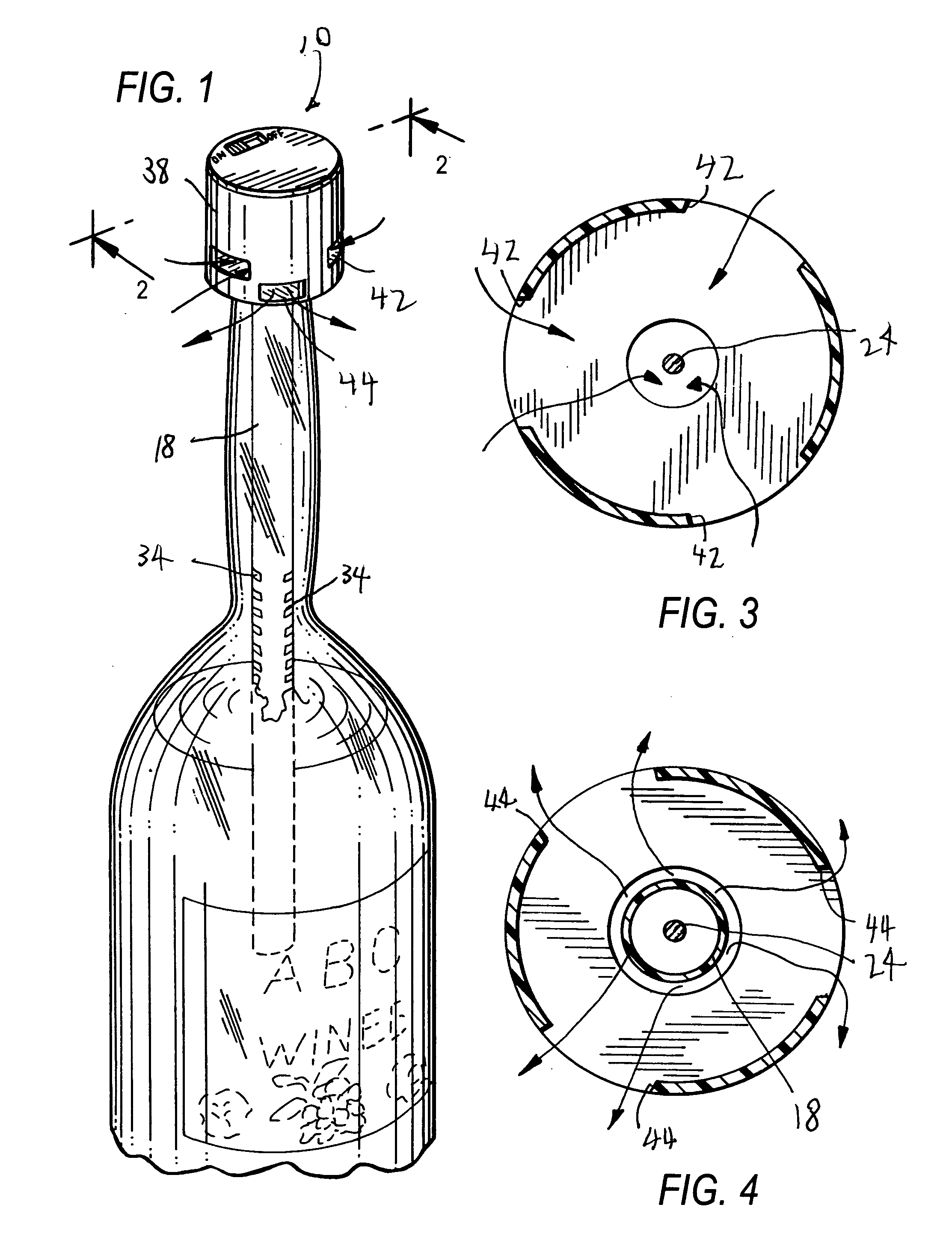
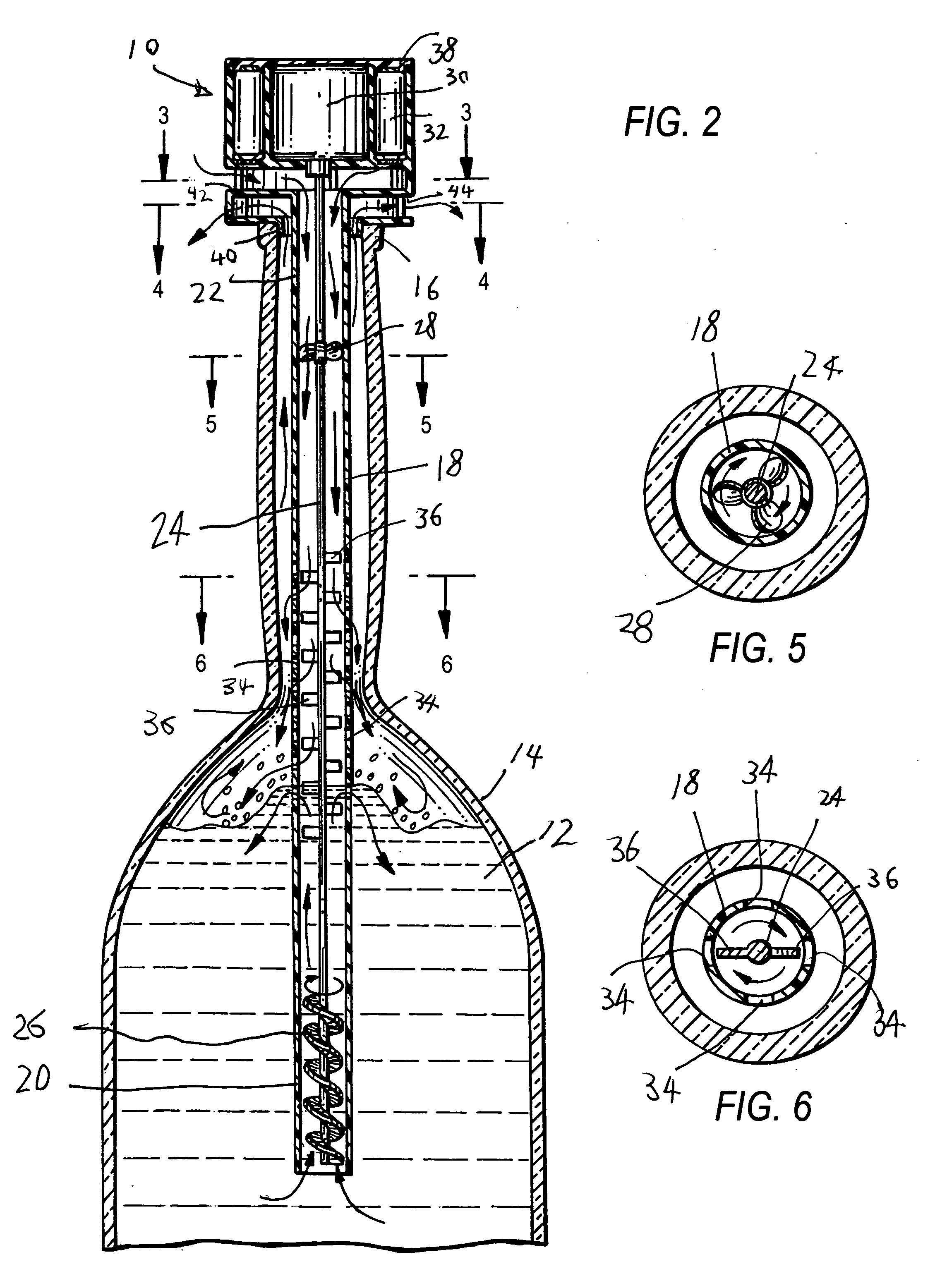
[0016]Referring now to the drawings, reference numeral 10 generally identifies a portable aeration device for aerating wine 12 in a bottle 14 having a neck 16. The device 10 includes an elongated, upright, hollow conduit 18 having one or lower end region 20 immersed in the wine 12 to be in fluid communication with the wine 12, and an opposite or upper end region 22 exposed to the atmosphere to be in fluid communication with the atmosphere.

[0017]A rotary shaft 24 is located within, and extends along, the conduit 18. A set of wine blades 26, preferably configured as a single, continuous, spiral blade, is mounted on the shaft 24 inside the conduit 18 for drawing the wine 12 as a wine flow into the lower end region 20 in an upward direction toward the upper end region 22 of the conduit 18 upon rotation of the shaft 24. Preferably, a set of air blades 28, including a single blade, is mounted on the shaft 24 inside the conduit 18 for causing the air to move, by pushing or pulling, as an a...


PUM

PropertyMeasurementUnit
centrifugal forceaaaaaaaaaa
rotationaaaaaaaaaa
timeaaaaaaaaaa

Abstract

A device for aerating wine in a bottle has an elongated, upright conduit with one end region immersed in the wine, and an opposite end region exposed to the atmosphere. A rotary shaft is located within, and extends along, the conduit. A wine blade is mounted on the shaft for drawing the wine as a wine flow into the one end region in an upward direction toward the opposite end region of the conduit upon rotation of the shaft. An air blade is preferably mounted on the shaft for causing the air to move as an air stream into the opposite end region in a downward direction toward the one end region of the conduit upon rotation of the shaft. A drive rotates the shaft, the wine blades and the air blades to propel the wine flow and the air stream against each other in a mutually countercurrent relationship and to commingle the wine flow and the air stream inside the bottle.

Description

BACKGROUND OF THE INVENTION[0001]This invention generally relates to the aeration or decanting of liquids stored in containers and, more particularly, to a device for, and a method of, aerating wine in bottles.[0002]To enjoy the bouquet and flavor of a fine wine, wine connoisseurs knew that the wine should be allowed to aerate or “breathe” before human consumption. Heretofore, this was done by merely opening a bottle of wine and allowing the wine to interact with the atmosphere in order to oxidize certain chemicals, such as tannins, naturally contained in the wine, which would otherwise impair the taste of the wine. This was a time consuming operation and needed to be performed well in advance of consumption of the wine. Wine was also conventionally aerated by manually decanting the wine from the wine bottle to another container. Here again, this transfer operation was time consuming and required not only a separate decanter, but also a steady hand to avoid wine spillage.[0003]In or...

Claims


Application Information

Patent Timeline
Patent Type & Authority Applications(United States)
IPC IPC(8): B01F3/04
CPCB01F3/04595B01F3/04609B01F2215/0072B01F2005/0034B01F7/166B01F23/2333B01F23/23341B01F2025/918B01F27/84B01F2101/17
Inventor CHENG, PETER S.
Owner CHENG PETER S
Why Eureka
Try Eureka