
Compressed air supply device for motor vehicles

a technology for compressed air and motor vehicles, which is applied in the direction of positive displacement liquid engines, machines/engines, instruments, etc., can solve the problems of reducing accuracy, affecting the capacitance principle, and contaminating the compressed air in commercial vehicles with different constituents of the intake air, so as to reduce the harmful effects of contaminants and prevent the influence of humidity measurement

Active Publication Date: 2010-03-11
ZF CV SYST EURO BV
View PDF6 Cites 8 Cited by
  • Summary
  • Abstract
  • Description
  • Claims
  • Application Information

AI Technical Summary

Benefits of technology

The present invention provides a compressed air supply device for motor vehicles that overcomes deficiencies of conventional devices. The device includes a compressor, control electronics, an air dryer, a dehumidification device, a pressure regulator, a multi-circuit safety valve, a regeneration valve, and a moisture sensor. The invention also includes a bypass duct with smaller cross section and volume flow than the actual compressed air line, which reduces the impact of contaminants on the moisture sensor and preserves its calibrated accuracy over a longer time period. The measurement of relative humidity in the bypass duct can be done either directly downstream from the air dryer or in the working circuit of the multi-circuit safety valve. The bypass duct can be designed to develop turbulent flow or placed in communication with the compressed air line to drain excess moisture and contaminants. The invention aims to reduce the harmful effects of contaminants on the polymer layer of the moisture sensor and prevent influence on humidity measurement accuracy and useful life due to harmful impurities and constituents of the compressed air.

Problems solved by technology

As is known, the compressed air in commercial vehicles is contaminated with different constituents of the intake air, some harmful for the polymer layer, and with harmful oil and oil-decomposition products from the compression process in the compressor.
As a result, the effectiveness of the capacitive principle is greatly impaired by such contaminants after a prolonged exposure time, thus, in particular, reducing the accuracy and shortening the useful life of the moisture sensor.

Method used


Image

  • Compressed air supply device for motor vehicles
  • Compressed air supply device for motor vehicles
  • Compressed air supply device for motor vehicles

Examples


Embodiment Construction

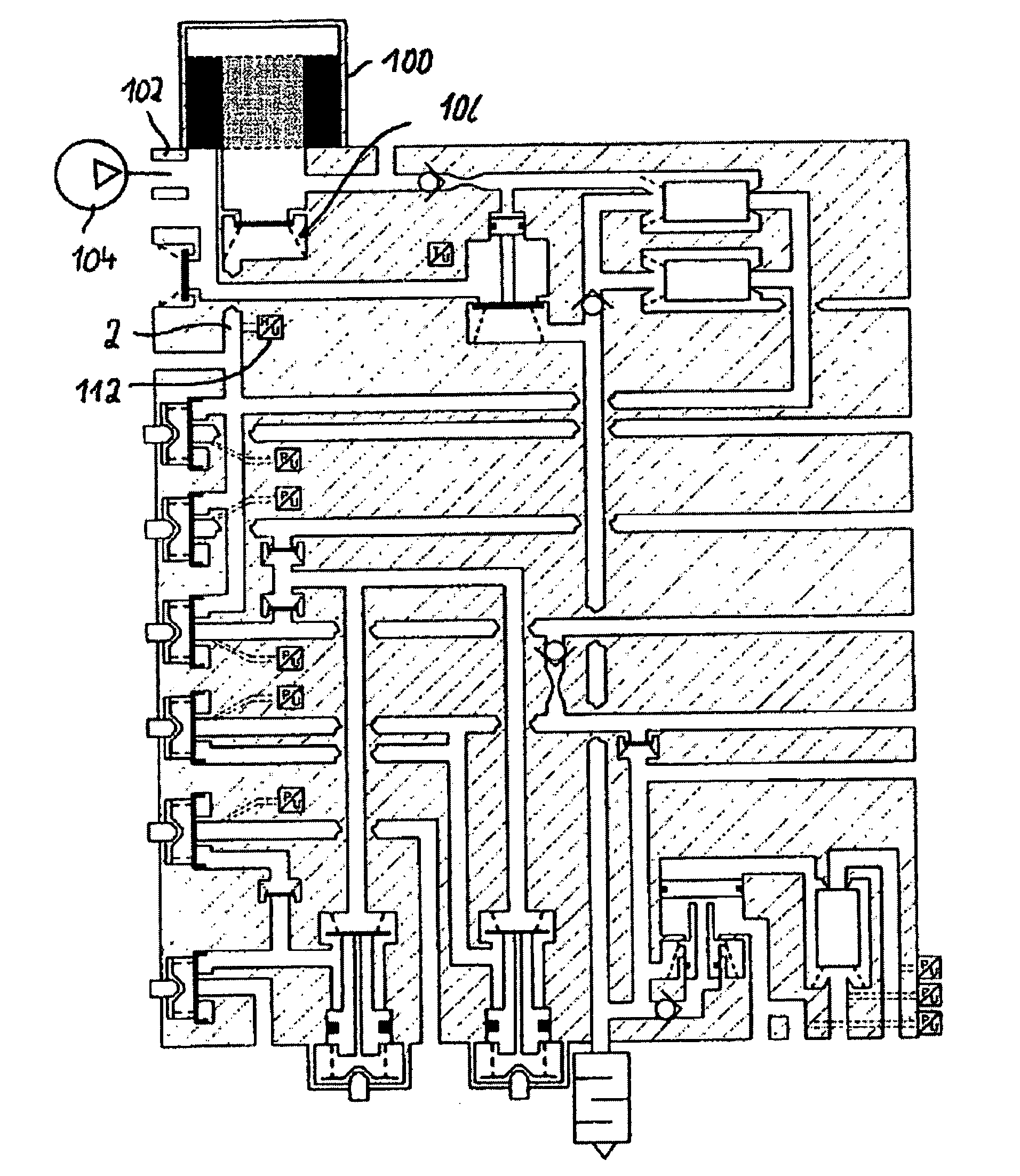
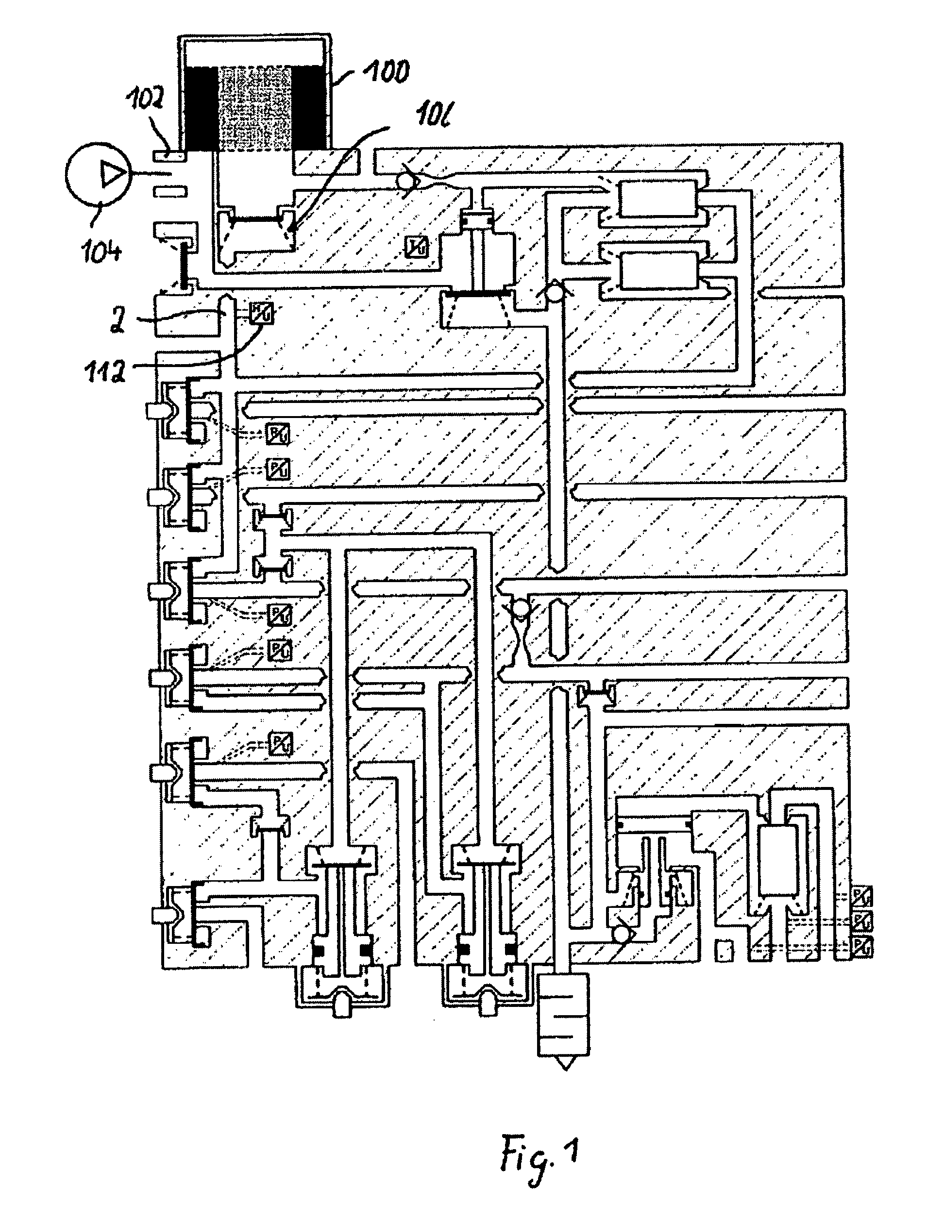
[0016]Referring now to the drawing figures, FIG. 1 shows a compressed air supply device for motor vehicles, with a compressed air dryer 100, to which compressed air from a compressor 104 is fed via a port 102. The compressed air flows through compressed air dryer 100 and then flows further via a check valve 106 and a compressed air line 2 to a multi-circuit safety valve 110, which is not the subject of the present application and, therefore, is not discussed in greater detail hereinafter.

[0017]A moisture sensor 112 is disposed in pressure line 2 leading to the multi-circuit safety valve.

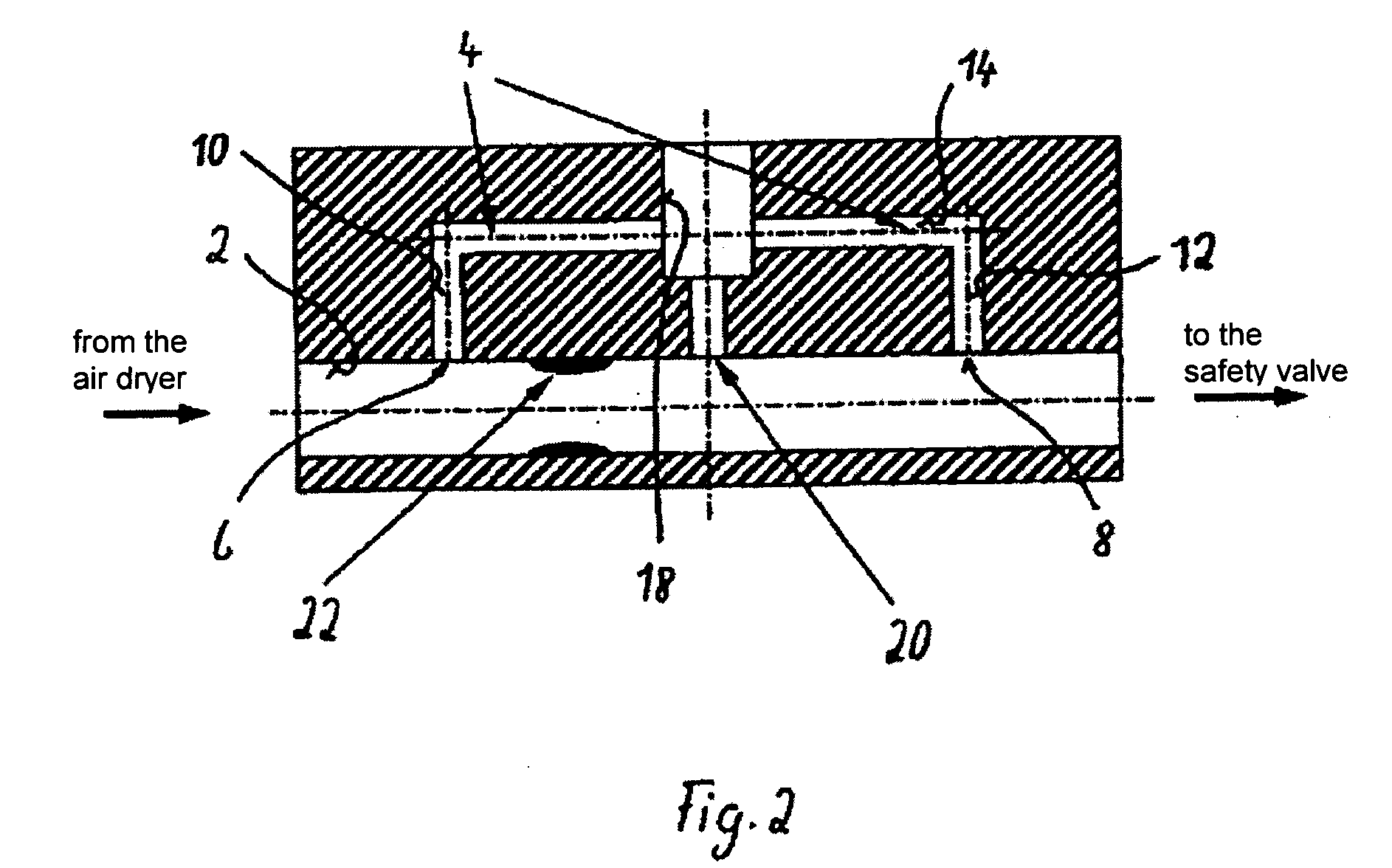
[0018]According to embodiments of the present invention, the moisture measurement by means of moisture sensor 112 takes place not directly in compressed air line 2 on the outlet side of compressed air dryer 100 but, rather, in a bypass duct 4 of pressure line 2, as is illustrated in more detail in FIG. 2. Thus, bypass duct 4 is provided between the outlet of compressed air dryer 100 and multi-circuit...


PUM


Abstract

A compressed air supply system for motor vehicles includes a compressor, control electronics, an air dryer having an inlet channel for non-dried compressed air, an outlet channel for the dried compressed air, and a dehumidification device through which the compressed air to be dried can flow, a pressure regulator having an outlet valve for controlling the compressor between an idle phase and a load phase, a multi-circuit safety valve that is connected to the outlet channel of the air dryer via a compressed air line, and over-flow valves for the individual circuits, a regeneration valve and a moisture sensor for detecting the atmospheric moisture in the compressed air flowing in the compressed air line. To reduce the detrimental effects of admixtures and components of the compressed air on the moisture sensor, the moisture sensor is located in a bypass channel of the compressed air line.

Description

FIELD OF THE INVENTION[0001]The present invention generally relates to a compressed air supply device for motor vehicles.BACKGROUND OF THE INVENTION[0002]In compressed air supply devices of motor vehicles, it is known how to measure the relative humidity at the outlet of the air dryer or in a compressed air tank by means of a moisture sensor designed as a moisture switch, the output signals of which are supplied to evaluation / control electronics. In the event that the relative humidity exceeds a threshold value, the evaluation / control electronics initiate regeneration of the dehumidification device or generate a warning signal to indicate, for example, that the dehumidification device has greatly deteriorated in terms of efficiency and / or that it must be replaced. As an improvement of the moisture switch, capacitive moisture sensors, in which a hygroscopic polymer layer, for example, is disposed as a dielectric between two capacitor electrodes, are, among other options, also used. D...

Claims


Application Information

Patent Timeline
Patent Type & Authority Applications(United States)
IPC IPC(8): F04B49/00
CPCG01N1/2247B60T17/02Y10T137/85986
Inventor DIEKMEYER, HEINRICHHEINRICH, HORSTSTRILKA, BERND
Owner ZF CV SYST EURO BV
Learn More