Permanent magnet rotating electrical machine and permanent magnet motor drive system

Inactive Publication Date: 2010-03-11
KK TOSHIBA
View PDF12 Cites 42 Cited by
  • Summary
  • Abstract
  • Description
  • Claims
  • Application Information

AI Technical Summary

Benefits of technology

[0022]An aspect of the present invention provides a permanent magnet motor drive system having a permanent magnet motor employing permanent magnets, an inverter to drive the permanent magnet motor, and a magnetize means to pass a magnetizing current for controlling flux of the permanent magnets. The permanent magnet motor employs two or more kinds of permanent magnets having different shapes or magnetic characteristics, to form each magnetic pole. A plurality of the magnetic poles form a rotor. The magnetize means passes for a short time a d-axis current through an armature coil of the permanent magnet motor, to generate a magnetic field to magnetiz

Problems solved by technology

The rotating electrical machine of the Patent Document 4 is a simple alnico magnet motor, and therefore, its output is insufficient.
Then, it will be difficult to magnetize the permanent magnets, or change the flux amount of the permanent magnets.
The voltage induced by the permanent magnet is applied to electronic parts of an inverter, and if the applied voltage exceeds a withstand voltage of the electronic parts, the parts will cause insulation breakage.
Such a design, however, lowers the output and efficiency of the permanent magnet rotating electrical machine in a low-speed zone.
Always passing a negative d-axis current that contributes nothing to an output, however, increases a copper loss to d

Method used


Image

  • Permanent magnet rotating electrical machine and permanent magnet motor drive system
  • Permanent magnet rotating electrical machine and permanent magnet motor drive system
  • Permanent magnet rotating electrical machine and permanent magnet motor drive system

Examples


first embodiment

[0048][Permanent Magnet Rotating Electrical Machine]

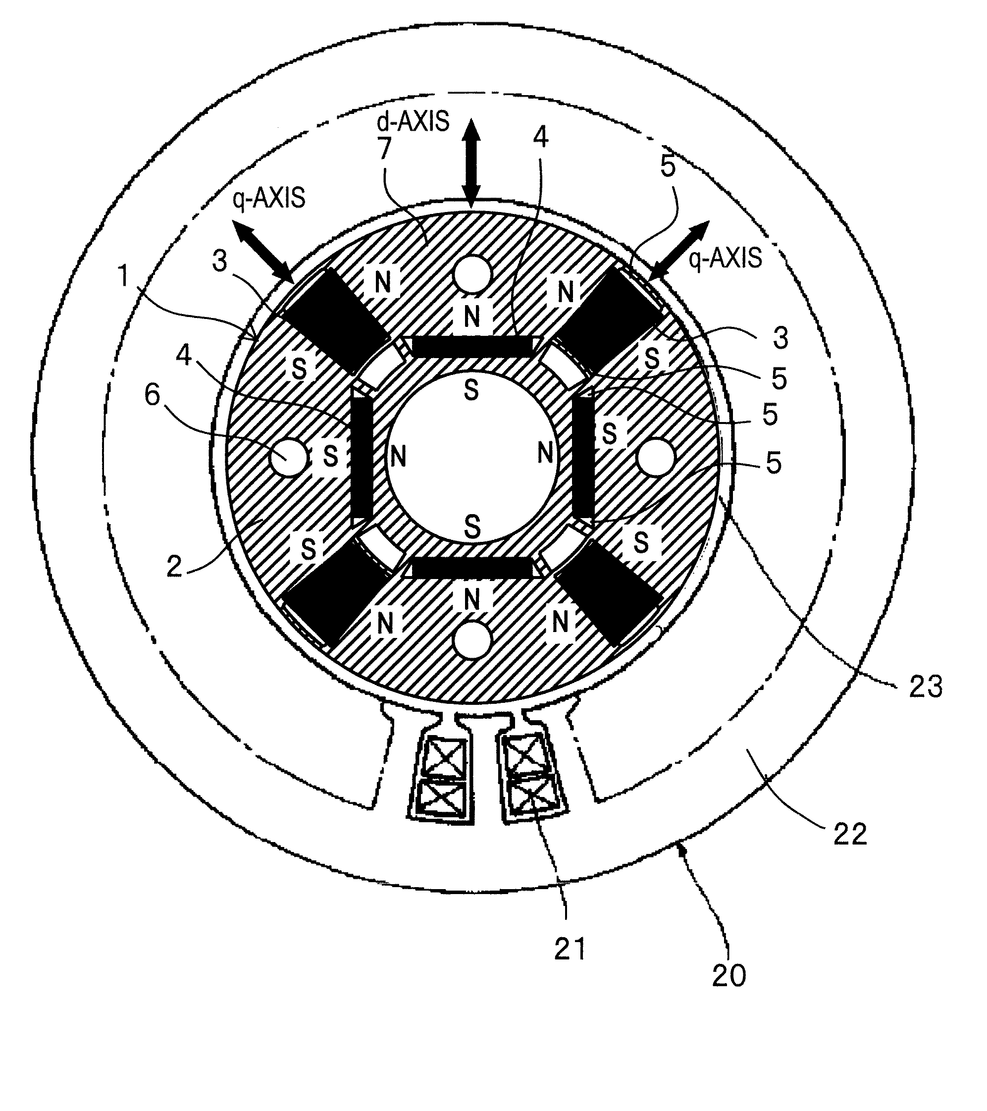
[0049]With reference to FIGS. 1 to 6, the permanent magnet rotating electrical machine according to the first embodiment of the present invention will be explained. FIG. 1 illustrates a structure of the permanent magnet rotating electrical machine according to the embodiment. Inside a stator 20, a rotor 1 is accommodated to face the stator 20 with an air gap 23 interposing between them. The stator 20 is a conventional one and is similar to that illustrated in FIG. 20.

[0050]As illustrated in FIG. 1, the rotor 1 in the permanent magnet rotating electrical machine according to the embodiment includes a rotor core 2, permanent magnets 3 whose product of coercive force and thickness along magnetizing direction is small, and permanent magnets 4 whose product of coercive force and thickness along magnetizing direction is large. The rotor core 2 is constituted by laminating silicon steel plates. The permanent magnet 3 whose product of coer...

second embodiment

[0113]A permanent magnet rotating electrical machine and permanent magnet motor drive system according to the second embodiment of the present invention will be explained. This embodiment is characterized in that the permanent magnet rotating electrical machine 101 illustrated in FIG. 1 receives a pulse-like magnetic field created by a short-time d-axis current provided by the permanent magnet motor drive system illustrated in FIG. 7, to irreversibly magnetize the alnico permanent magnets 3 and change a linkage flux amount.

[0114]In this way, flux by a negative d-axis current is always created in a middle or high rotation speed zone, so that linkage flux consisting of the flux by the negative d-axis current and flux by the permanent magnets 3 and 4 is adjusted according to the flux by the negative d-axis current. Namely, in the middle or high speed zone, the pulse-like magnetic field created by a short-time d-axis current irreversibly changes the magnetized state of the alnico perman...

third embodiment

[0116]A permanent magnet rotating electrical machine according to the third embodiment of the present invention will be explained with reference to FIG. 13. The structure of a stator 20 in the permanent magnet rotating electrical machine of the embodiment is the same as that of the first embodiment illustrated in FIG. 1 and that of the related art illustrated in FIG. 20.

[0117]As illustrated in FIG. 13, a rotor 1 of this embodiment arranges each alnico permanent magnet 3 inside a rotor core 2 along a q-axis in a diametrical direction and each NdFeB permanent magnet 4 inside the rotor core 2 in a circumferential direction orthogonal to a d-axis. An inner circumferential side of the rotor core 2 of the rotor 1 is engaged with an iron shaft 9. The shaft 9 has four cut faces to form an air layer 8 between the rotor core 2 and the shaft 9. The shaft 9 may be made of a nonmagnetic material.

[0118]An armature coil 21 passes a current to generate a magnetic field for magnetizing the permanent...


PUM

PropertyMeasurementUnit
Temperatureaaaaaaaaaa
Thicknessaaaaaaaaaa
Forceaaaaaaaaaa

Abstract

A permanent magnet rotating electrical machine capable of conducting a variable speed operation at high output in a wide range from low speed to high speed and improving efficiency and reliability in a wide operating range. Two kinds of permanent magnets having different shapes or different magnetic characteristics are embedded in a rotor core, to form a magnetic pole. The permanent magnets arranged at the magnetic pole include a permanent magnet whose product of coercive force and thickness along a magnetizing direction is small and the permanent magnet whose product of coercive force and thickness along the magnetizing direction is large. A magnetic field created by passing a current to an armature coil for a short time is used to irreversibly magnetize the permanent magnet whose product of coercive force and thickness along magnetizing direction is small, thereby changing a total linkage flux amount, and a positive d-axis current is passed when torque is large.

Description

TECHNICAL FIELD[0001]The present invention relates to a permanent magnet rotating electrical machine and a permanent magnet motor drive system.BACKGROUND TECHNOLOGY[0002]Generally, permanent magnet rotating electrical machines are classified into two types. One is a surface-permanent magnet rotating electrical machine having permanent magnets adhered to an outer circumferential face of a rotor core and the other is an interior permanent magnet rotating electrical machine having permanent magnets embedded in a rotor core. For a variable-speed drive motor, the interior permanent magnet rotating electrical machine is appropriate.[0003]With reference to FIG. 20, a configuration of a conventional interior permanent magnet rotating electrical machine will be explained. Along an outer circumference of a rotor core 2 of a rotor 1, rectangular hollows are arranged at regular intervals, the number of the rectangular hollows being equal to the number of poles. In FIG. 20, the rotor 1 has four ...

Claims


Application Information

Patent Timeline
IPC IPC(8): H02P7/06H02K21/14H02K1/27H02P21/00H02P21/02H02P21/13H02P21/22H02P23/02H02P23/16H02P23/28H02P27/04H02P27/08
CPCH02K1/2766H02P21/06Y10T29/49822Y10T29/49009H02P2207/05H02P23/0086H02P21/0089
Inventor SAKAI, KAZUTOYUUKI, KAZUAKI
Owner KK TOSHIBA
Why Eureka
Try Eureka