Active antennas for multiple bands in wireless portable devices

a wireless portable device and active antenna technology, applied in the direction of antenna supports/mountings, radio transmission, transmission, etc., can solve the problems of multiple antennas, affecting the mechanical design affecting the quality etc., to simplify the mechanical design and layout of wireless portable devices, reduce the cost of materials, and reduce the variance in the manufacturing of different devices. , the effect of simplifying the antenna structur

Active Publication Date: 2010-03-11
RAPPAPORT THEODORE S
View PDF5 Cites 131 Cited by
  • Summary
  • Abstract
  • Description
  • Claims
  • Application Information

AI Technical Summary

Benefits of technology

[0017]The current invention uses one or more antennas, at least one of which can be used by multiple transmitters or receivers in different bands, thereby greatly simplifying the antenna structures in a portable wireless device, and greatly reducing the mechanical design complexity, the cost of bill of materials, and the variance in manufacturing of different devices of a particular model.
[0018]The current invention exploits the idea of active antenna tuning, but expands it greatly in a non-obvious way by applying the concepts to the situation of where multiple band transmitters, receivers, or transceivers must be used simultaneously

Problems solved by technology

Computer makers and cellphone makers have difficulty with the mechanical design of their equipment, and spend a great deal of engineering time, research, and cost in manufacture for the bill of materials for the feedlines and connections between transmitter circuits, transceiver circuits, or receiver circuits and the antennas that are mounted or housed in the wireless device casing.
Similar problems exist with cellphones, and all devices generally must meet or exceed certain federal or wireless carrier-im

Method used


Image

  • Active antennas for multiple bands in wireless portable devices
  • Active antennas for multiple bands in wireless portable devices
  • Active antennas for multiple bands in wireless portable devices

Examples


Embodiment Construction

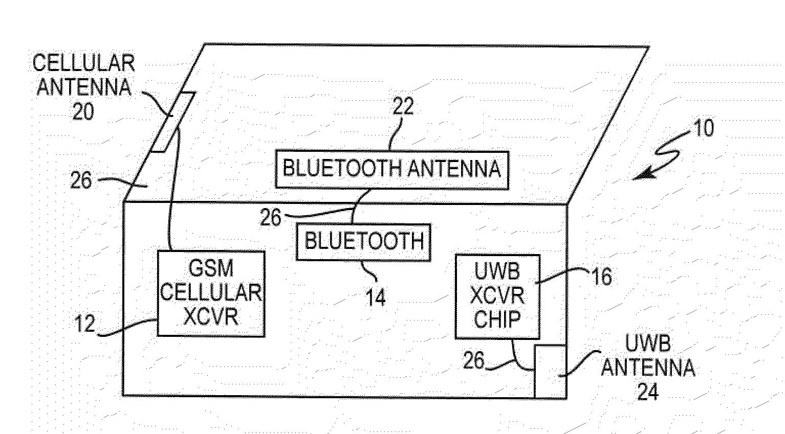
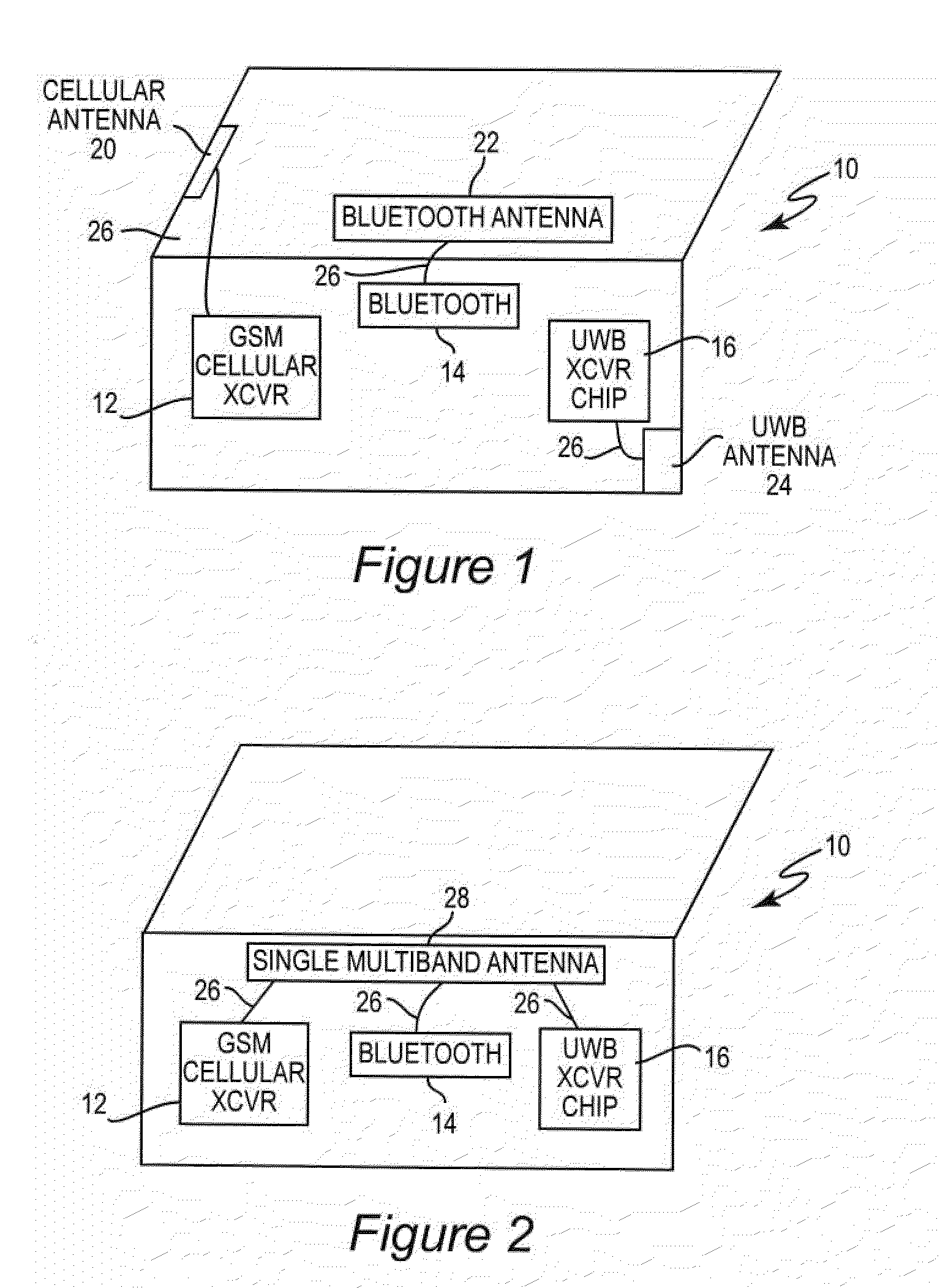
[0026]Shown in FIG. 1 is an example of how cellphones or laptops or other wireless devices 10 arc designed today. In general, different band transceivers (e.g., GSM cellular transceiver 12, Bluetooth transceiver 14, and ultrawideband transceiver 16) are connected to different antennas (e.g., cellular antenna 20, Bluetooth antenna 22, and UWB antenna 24) that must he affixed to, located within the packaging of the device, or included in the printed circuit boards of the device, thereby taking up space, feedline resources (e.g., feedlines 26), increasing the bill of materials, and adding complexity.

[0027]FIG. 2 illustrates the basic idea of the present invention which can he implemented in fixed or mobile wireless devices 10 such as computers, telephones, portable computing or communication devices, games, wireless post it notes, wireless memory media, personal data assistants and navigation assistants. One potential application of the invention is in the IEEE 802.11ad standard, where...


PUM


Abstract

Wireless devices, and particularly mobile devices such as cellphones, PDAs, computers, navigation devices, etc., as well as other devices which transmit or receive data or other signals at multiple frequency bands utilize at least one antenna to transmit and receive and a plurality of different bands (e.g., GSM cellular communication band; Bluetooth short range communication band; ultrawideband (UWB) communications, etc.). These wireless devices can simultaneously transmit or receive at a plurality of different bands, or simultaneously transmit and receive at different bands. The wireless devices have the ability to use a single physical structure (e.g., an antenna) for transmission and reception of many different bands. The antenna can be either actively tuned or passively tuned using one or more elements.

Description

CROSS-REFERENCE TO RELATED APPLICATIONS[0001]This application claims priority to U.S. Provisional Application Ser. No. 61 / 088,829, entitled “Single Active Antenna for Multiple Bands in Wireless Portable Devices”, filed Aug. 14, 2008, and the complete contents thereof is incorporated by referenceBACKGROUND OF THE INVENTION[0002]1. Field of the Invention[0003]The present invention relates to wireless portable devices and particularly to improvements in transmitting and receiving electromagnetic signals at multiple frequency bands.[0004]2. Background of the Invention[0005]Today's wireless devices, such as laptops and computers that connect wirelessly to the cellphone network or internet must use antennas to transmit and receive wireless energy to and from the device. Today's cellphones and laptops typically require multiple antennas, each antenna designed for resonance or desired performance at a particular frequency band (such as cellular band, say in the 850-950 MHz band, the Bluetoo...

Claims


Application Information

Patent Timeline
IPC IPC(8): H01Q1/24H01Q5/335H01Q5/357
CPCH01Q1/243H04B1/0053H01Q5/357H01Q5/314H01Q5/335H01Q5/0031
Inventor RAPPAPORT, THEODORE S.
Owner RAPPAPORT THEODORE S
Why Eureka
Try Eureka