Optical Device Exhibiting Color Shift Upon Rotation

a technology of optical devices and rotation, applied in the field of optical devices, can solve the problems of counterfeiting of optical devices, banknote security applications, and thicknesses that are thicker than the required 1 mil or 25 microns,

Active Publication Date: 2010-03-11
VIAVI SOLUTIONS INC
View PDF31 Cites 33 Cited by
  • Summary
  • Abstract
  • Description
  • Claims
  • Application Information

AI Technical Summary

Benefits of technology

[0023]In accordance with another aspect of the invention, the substrate has first and second areas shaped so as to form indicia discernible by color. Furthermore, the coating can have a transparent cover layer occupying at least a fr...

Problems solved by technology

Unfortunately, the holographic devices can be counterfeited by shining a laser beam on the device and recording the diffracted image, or simply by mechanically replicating the holographic surface relief pattern.
A major drawback of the microlens arrays devices for a banknote security application is that they tend to be thicker than required 1 mil, or 25 microns thickness.
Incorporating thick security devices into a banknote causes it to be slightly thicker on one end than on the other, which causes a stack of such banknotes to tilt towards one s...

Method used


Image

  • Optical Device Exhibiting Color Shift Upon Rotation
  • Optical Device Exhibiting Color Shift Upon Rotation
  • Optical Device Exhibiting Color Shift Upon Rotation

Examples


Embodiment Construction

[0059]While the present teachings are described in conjunction with various embodiments and examples, it is not intended that the present teachings be limited to such embodiments. On the contrary, the present teachings encompass various alternatives, modifications and equivalents, as will be appreciated by those of skill in the art.

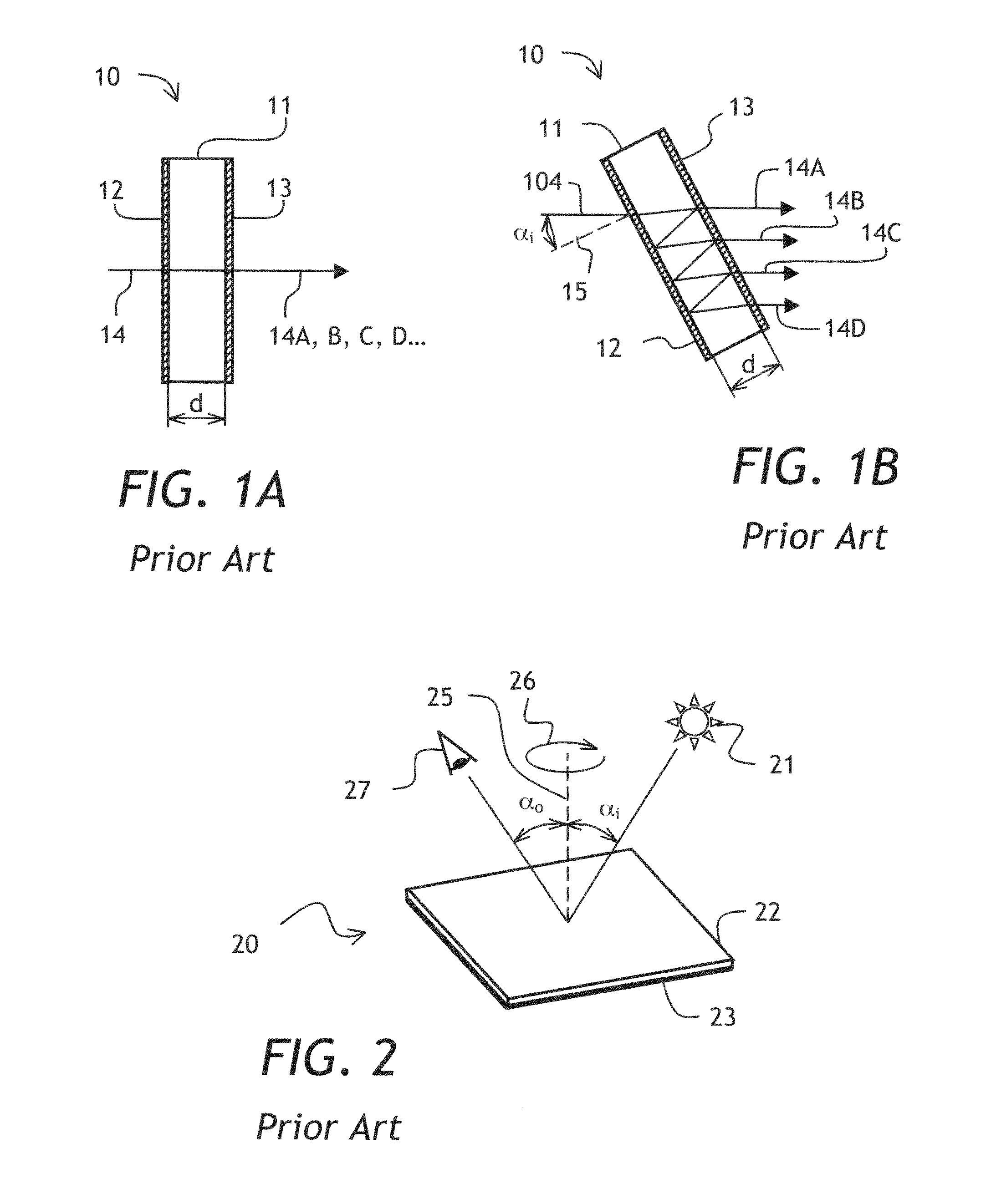
[0060]Referring to FIG. 1A, a prior-art thin film interference filter 10 is shown having a transparent layer 11 of thickness d sandwiched between partial reflectors 12 and 13. An incoming multi-color optical beam 14, upon multiple reflections between the partial reflectors 12 and 13, exits the thin film interference filter 10 as beams 14A, 14B, 14C, 14D . . . , which interfere constructively or destructively, depending on ratio of wavelength to the optical path length within the transparent layer 11, which in this case is equal to thickness d of the transparent layer 11 multiplied by index of refraction of the transparent layer 11. Turning now to FIG. 1B,...


PUM


Abstract

An optical device exhibiting a color shift upon rotation is disclosed. The optical device has a textured surface having a relief structure finer than a human eye resolution but large enough not to exhibit diffraction effects. The textured surface is coated with an interference thin film that exhibits a color shift with tilt. A uniform color seen at one angle of rotation changes to another uniform color when the optical device is rotated in its own plane. A method of manufacturing of such an optical device, as well as the use of the optical device as an optical security and authentication element, is also disclosed.

Description

CROSS-REFERENCE TO RELATED APPLICATIONS[0001]The present invention claims priority from U.S. Provisional Patent Application No. 61 / 191,097, filed Sep. 5, 2008, which is incorporated herein by reference.TECHNICAL FIELD[0002]The present invention relates to optical devices exhibiting a change of perceived color upon changing an angle of illumination or angle of observation of the device, and in particular to optical devices that exhibit a color shift upon rotation of the device in its own plane relative to the observer.BACKGROUND OF THE INVENTION[0003]Color shifting pigments and colorants have been used in numerous applications, ranging from automobile paints to anti-counterfeiting inks for security documents and currency. Such pigments and colorants exhibit a property of changing color upon variation of an angle of incident light, or upon variation of a viewing angle of the observer. Color shifting pigments and foils are taught in U.S. Pat. No. 5,135,812 by Phillips et al., and color...

Claims


Application Information

Patent Timeline
IPC IPC(8): G02B5/28B05D5/06
CPCG02B5/286G02B5/285B42D15/00B29D11/00605B41M3/14B42D25/425B42D25/36B42D25/324B42D25/378B42D25/373
Inventor WITZMAN, MATTHEW R.SATERN, JASONPHILLIPS, ROGER W.BOUEVITCH, OLEG
Owner VIAVI SOLUTIONS INC
Why Eureka
Try Eureka