Image capturing apparatus and image capturing method

a technology of image capturing apparatus and image capturing method, which is applied in the direction of electronic editing digitised analogue information signals, instruments, color signal processing circuits, etc., can solve the problems of difficult application of high-speed image capturing systems, complicated device structure, and process time to decode, so as to reduce power consumption and circuit scale

Active Publication Date: 2010-03-11
SONY CORP
View PDF10 Cites 51 Cited by
  • Summary
  • Abstract
  • Description
  • Claims
  • Application Information

AI Technical Summary

Benefits of technology

[0059]In the image capturing apparatus according to the present invention, although a screen rate of an image capturing device is high, a camera signal processing circuit is needed to always satisfy only a screen rate according t

Problems solved by technology

HEI 8-251492” was aimed to temporarily store a captured image in a storage device such as a VTR or a semiconductor memory, reproduce the captured image in slow motion, and analyze a very high speed motion and the device itself had a complicated structure and was expensive.
Thus, it was difficult to apply high speed image capturing systems as described in Patent Document 1 or Patent Document 2 to portable image capturing devices that have been widespread as home-use devices, so-called camcorders (produc

Method used


Image

  • Image capturing apparatus and image capturing method
  • Image capturing apparatus and image capturing method
  • Image capturing apparatus and image capturing method

Examples


second embodiment

[0099]Next, with reference to FIG. 7, an image capturing apparatus 300 according to the present invention will be described. In the image capturing apparatus 300, a compression and decompression circuit 301 is disposed between a conversion processing section 201 and a recording device control circuit 210. The compression and decompression circuit 301 performs a compression-encoding process according to an encoding system, for example, JPEG (Joint Photographic Experts Group) or the like for raw data of the high screen rate received from the conversion processing section 201. Compression-encoded data are written to a recording device 111 under the control of the recording device control circuit 210. As the compression-decompression encoding system, a binary data encoding system may be used instead of the JPEG.

first embodiment

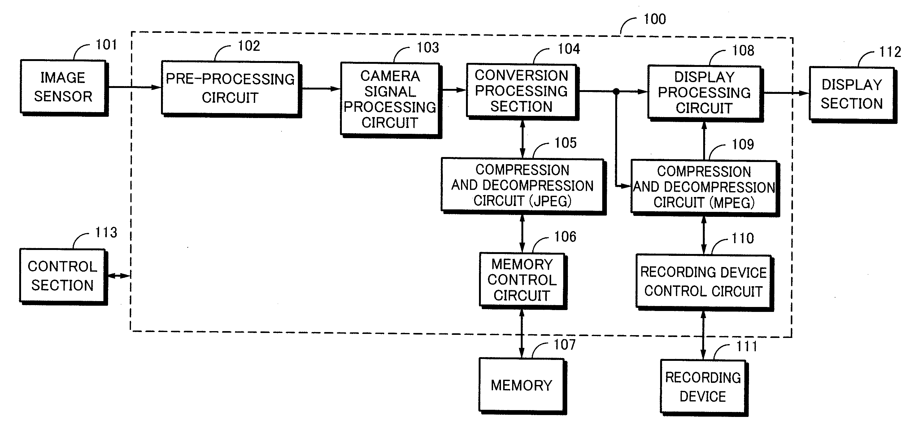
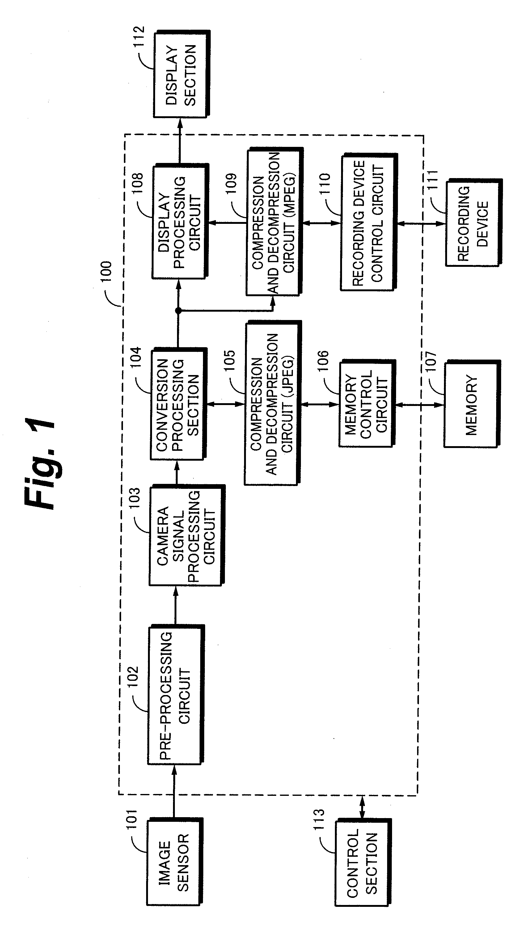
[0100]FIG. 8 shows signal flows in the recording state. Raw data of the high screen rate obtained in the high speed image capturing mode are compression-encoded by the compression and decompression circuit 301 and the compression-encoded data are recorded on a recording device 111 through the recording device control circuit 210. Like the first embodiment, an image signal whose screen rate has been converted into the regular screen rate by the conversion processing section 201 and that has been processed by the pre-processing circuit 202 and the camera signal processing circuit 203 is displayed on the display section 112.

[0101]As shown in FIG. 9, in the reproducing state, encoded data of raw data that have been read from the recording device 111 and supplied from the recording device control circuit 210 is expansion-decoded by the compression and decompression circuit 301. Expansion-decoded raw data are supplied from the conversion processing section 201 to the display section 112 t...

third embodiment

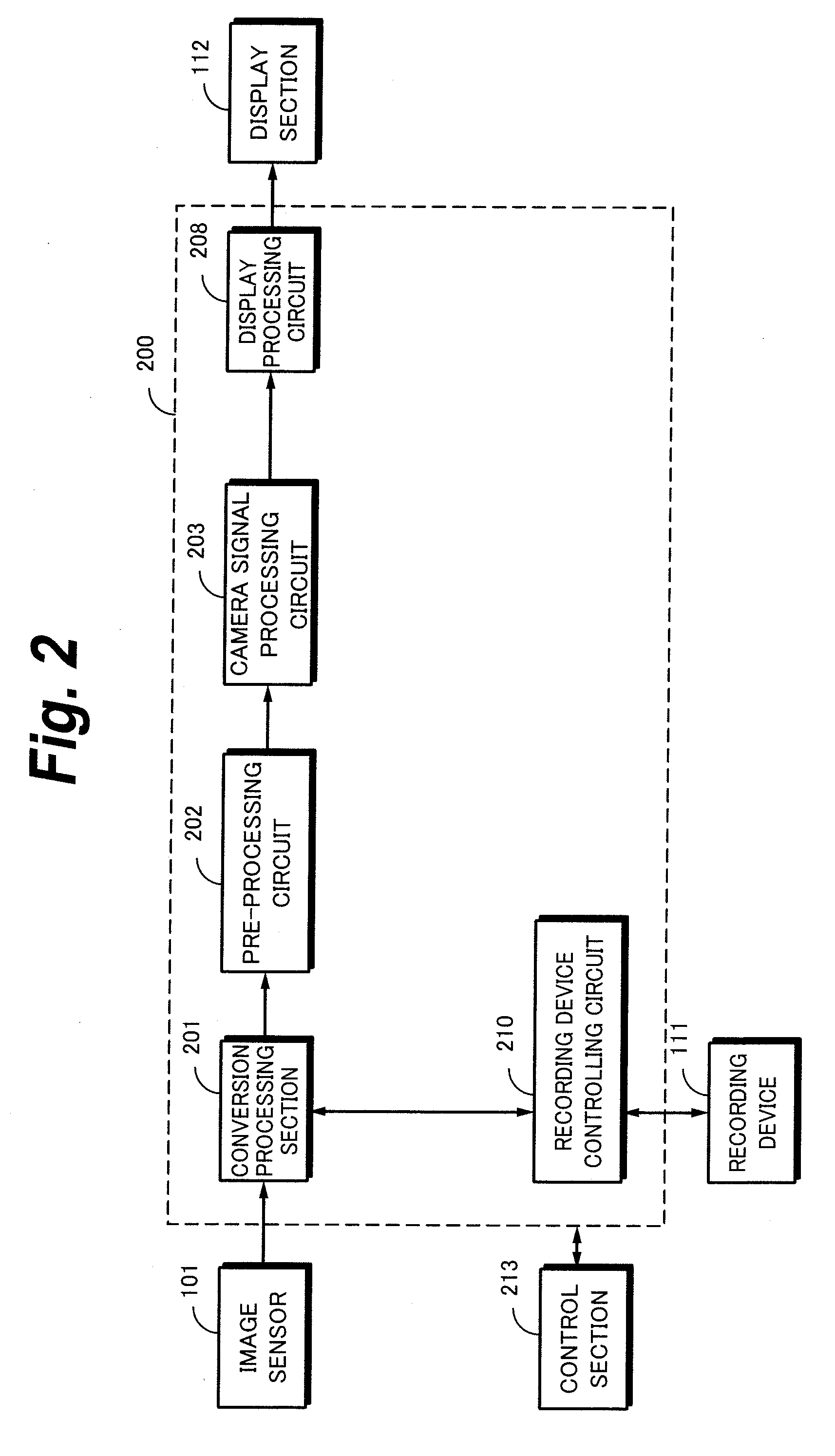
[0102]Next, with reference to FIG. 10, an image capturing apparatus 400 according to the present invention will be described. In the image capturing apparatus 400, a simple pre-processing circuit 401 and a simple camera signal processing circuit 402 are disposed downstream of a signal of a conversion processing section 201 so as to display a camera-through image that is being captured on the display section 112. “Simple” means that these circuits generate an image that is displayed only on the display section 112 and the image quality of an image to be displayed may be as low as that satisfying the purpose of checking for an image of an object being captured. For example, the number of bits of a signal displayed on the display section 112 is needed to be smaller than that of output data of an A / D converter of the pre-processing circuit 401. The simple pre-processing circuit 401 may be omitted. With the simple structure, power consumption and heat generation for which an image is mon...


PUM


Abstract

In a high speed image capturing state, a camera signal processing circuit is not needed to perform a signal process at a high screen rate, but at a regular screen rate. In the high speed image capturing mode, raw data of 240 fps received from an image sensor 101 are recorded on a recording device 111 through a conversion processing section 201 and a recording device controlling circuit 210. Raw data that have been decimated and size-converted are supplied to a camera signal processing circuit 203 through a pre-processing circuit 202 and an image being captured is displayed on a display section 112 with a signal for which a camera process has been performed. In a reproducing state, raw data are read from the recording device 111 at a low screen rate according to a display performance of the display section 112 and the raw data that have been read are processed are processed by the pre-processing circuit 202 and the camera signal processing circuit 203 and a reproduced image is displayed by the display section 112.

Description

TECHNICAL FIELD[0001]The present invention relates to an image capturing apparatus and an image capturing method, in particular, to those that capture images using a high speed image sensor.BACKGROUND ART[0002]In the past, high speed video cameras that can capture images at high speeds have been known. For example, a video camera has accomplished high speed image capturing by converting an image size per one image to be processed at a high speed rate into ¼ of the standard image size and placing these four images in an image of the regular rate (see Patent Document “Japanese Patent Application Laid-Open Publication No. HEI 8-88833”). Another video camera has accomplished high speed image capturing using a circuit structure that processes data received from a sensor in parallel so as to increase a process amount per unit time (see Patent Document “Japanese Patent Application Laid-Open Publication No. HEI 8-251492”).[0003]However, the high speed image capturing described in Patent Doc...

Claims


Application Information

Patent Timeline
IPC IPC(8): H04N3/15H04N5/228H04N5/917H04N5/225H04N5/232H04N101/00
CPCH04N5/232H04N5/23245H04N5/783H04N9/735H04N7/0127G11B31/006H04N5/77H04N7/0105H04N5/772H04N23/667H04N23/63H04N23/843H04N25/134H04N5/91H04N9/69H04N9/7904H04N9/80H04N9/87H04N23/88H04N23/10H04N23/60H04N23/951H04N25/75G11B27/005G11B27/031
Inventor KOSAKAI, RYOTAAIKI, KATSUTOSHISATO, NOBUYUKINAGAHAMA, HIROKISASE, MASATOSHIYONEDA, YUTAKA
Owner SONY CORP
Why Eureka
Try Eureka