

Method for producing hydrogen and sulphuric acid
- Summary
- Abstract
- Description
- Claims
- Application Information
AI Technical Summary
Benefits of technology
Problems solved by technology
Method used
Image

Examples
Embodiment Construction
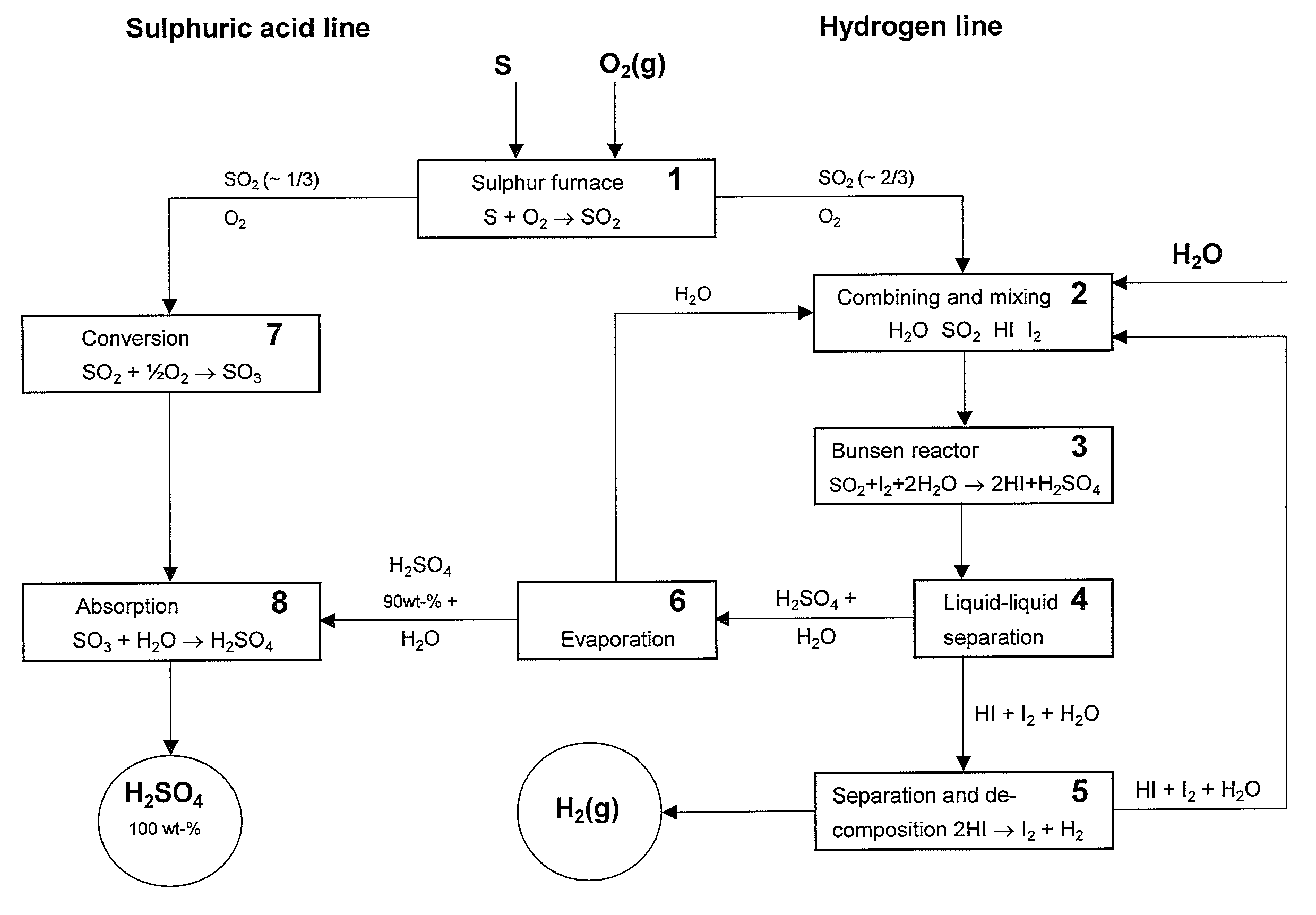
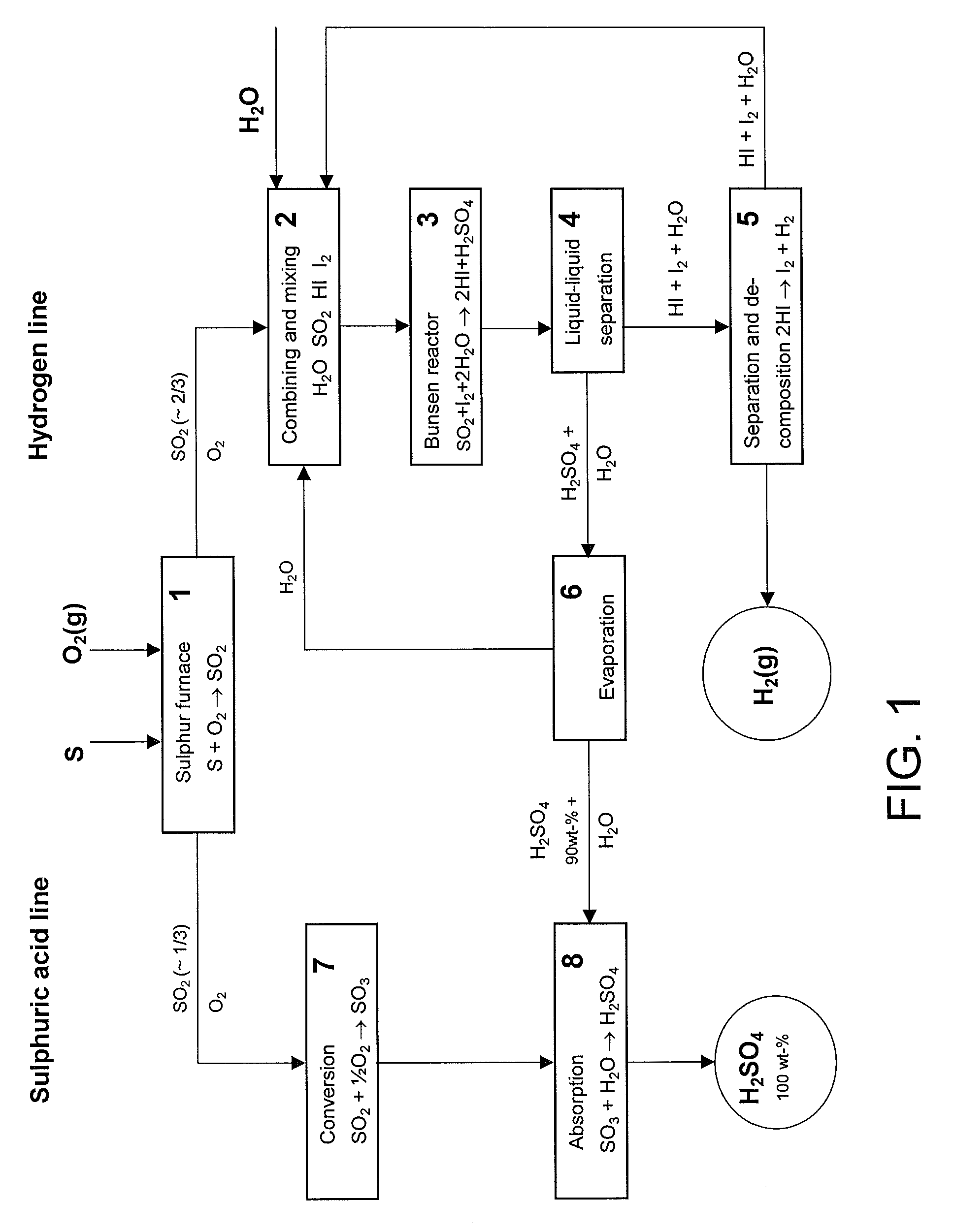
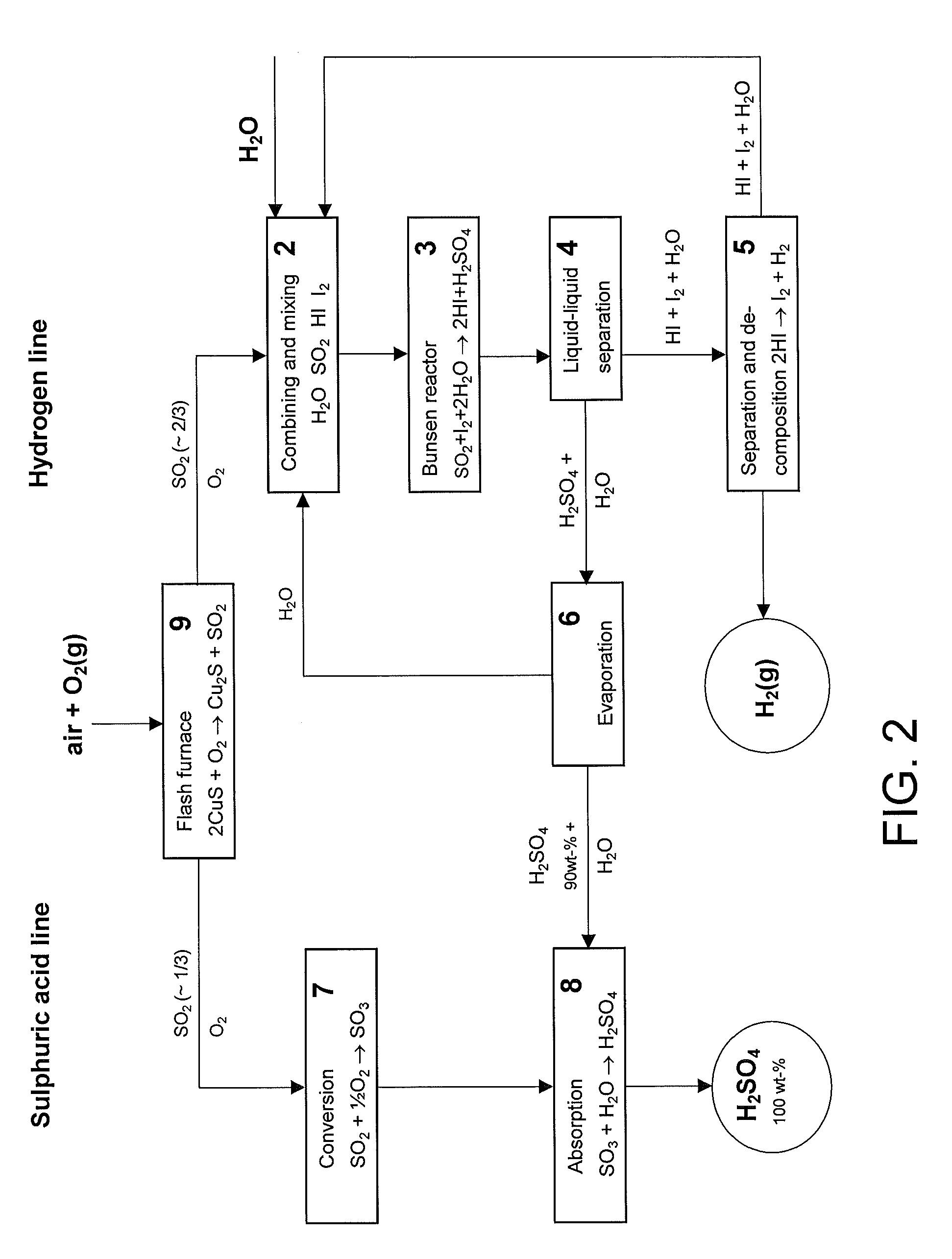
[0043]The main disadvantage in the prior art methods has been the big energy requirement of the sulphuric acid decomposition since it consumes roughly over 60% of the heat energy of the hydrogen production and only minor than to 40% is consumed in the decomposition of water. The methods described in the cited Japanese patent publications avoid sulphuric acid decomposition but however the production according to them must take place in connection of a sulphuric acid plant since the sulphuric acid produced is not commercial product as such.
[0044]The invention according to the present method reveals a new possibility to produce independently and cost-effectively both hydrogen and strong sulphuric acid (100%). In practice the acid content of the strong sulphuric acid is between 97-100 wt % though it is mentioned in the specification to be 100 wt %. It is also possible to produce oleum with the present method.
[0045]Some preferable process alternatives have been described in the light of ...
PUM
 Abstract
Description
Claims
Application Information