
Data transfer unit for computer

a data transfer unit and computer technology, applied in the field of data transfer units for computers, can solve problems such as equal processing speed, achieve the effects of reducing overheads caused by transmission of additional memory transactions to ensure completion of memory transactions transmitted via the plurality of interfaces, improving the effective performance of data transfer from the data transfer unit to the main memory, and improving the effect of data transfer

Inactive Publication Date: 2010-03-11
HITACHI LTD
View PDF20 Cites 26 Cited by
  • Summary
  • Abstract
  • Description
  • Claims
  • Application Information

AI Technical Summary

Benefits of technology

[0017]There is provided a data transfer unit that can improve throughput by suppressing contention of hardware resources on a path to a main memory or a main memory control unit among memory transactions transmitted to the main memory or the main memory control unit of a computer via a plurality of interfaces.
[0018]Further, there is provided a data transfer unit, which is coupled to a computer via a plurality of interfaces, and can maintain throughput of memory transactions for data transfer by guaranteeing completion of memory transactions and reducing overheads necessary for completion guaranteeing.
[0025]The first interface includes the plurality of interfaces, memory transactions transmitted to the main memory of the computer via the plurality of interfaces are transmitted, among the paths to the main memory, via a path in which contention of hardware resources is difficult to occur. Thus, effective performance of data transfer from the data transfer unit to the main memory can be improved.
[0026]Overheads caused by transmission of an additional memory transaction for guaranteeing completion of the memory transactions transmitted via the plurality of interfaces are reduced. Thus, effective performance of data transfer from the data transfer unit to the main memory can be improved.
[0027]The software operated on the computer can change a distribution method for memory transactions according to a configuration of the computer and characteristics of a user application that uses the data transfer unit. Thus, data transfer performance from the data transfer unit to the main memory can be improved. The change of the distribution method realizes a degenerate operation in which certain interfaces are cut off from the plurality of interfaces. As a result, even when abnormalities occur in certain interfaces, a data transfer unit that can continuously operate can be realized while data transfer performance is reduced.
[0028]As described above, this invention can improve data transfer performance from the data transfer unit to the main memory of the computer.

Problems solved by technology

In this case, the interconnect between the processors A and B needs to have a transfer speed at least twice as high as that of a path between the processor A and the I / O hub A or between the processor B and the I / O hub B. When the transfer speed of the interconnect between the processors A and B is equal to that of another path, there is a problem that, even if memory transactions are distributed, a processing speed is equal to that in the case where a memory transaction is executed by one interface.

Method used


Image

  • Data transfer unit for computer
  • Data transfer unit for computer
  • Data transfer unit for computer

Examples


first embodiment

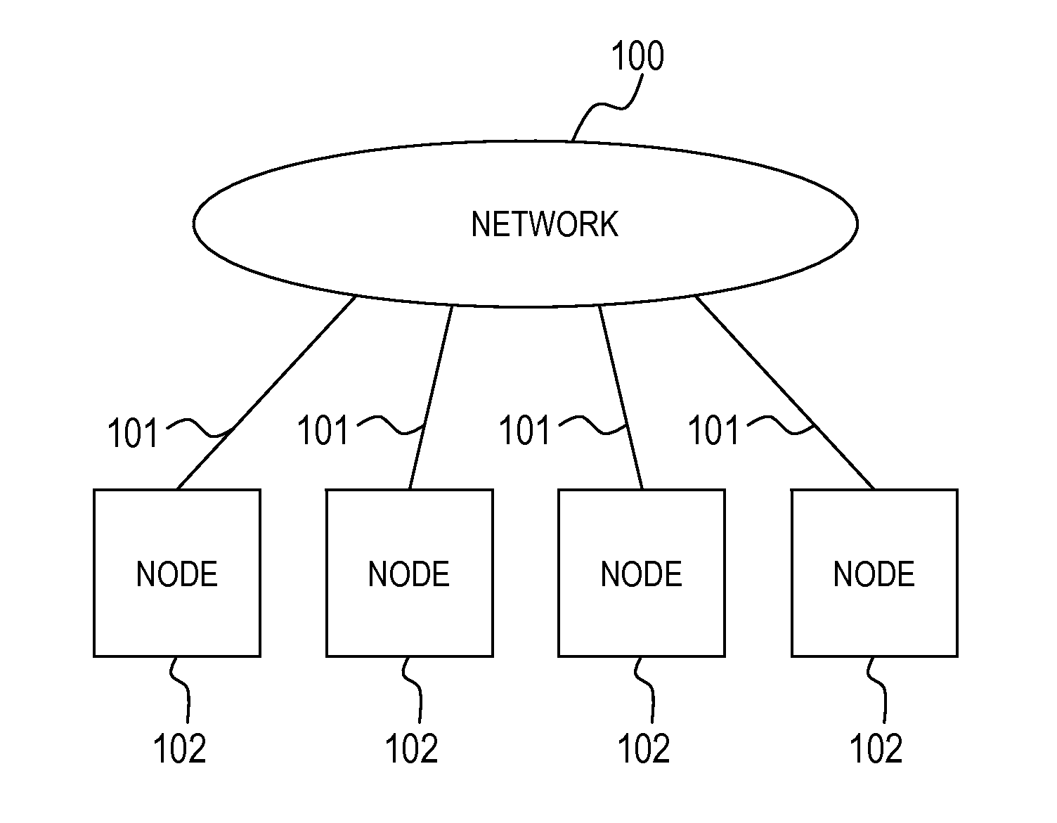
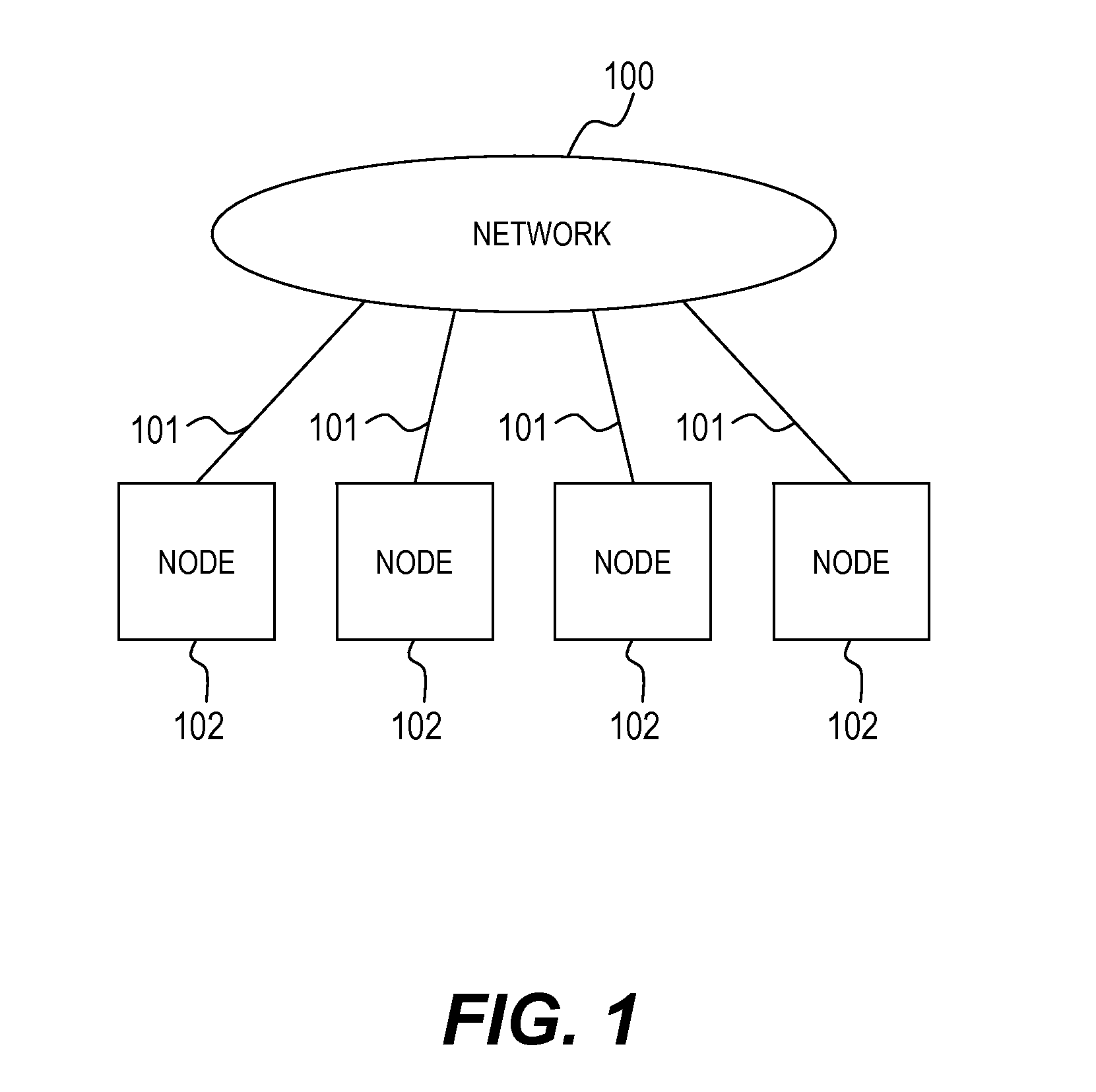
[0054]FIG. 1 illustrates a network realized by the network interface adaptor that is the data transfer unit according to the embodiment of this invention.

[0055]A network 100 is, for example, a network configured by InfiniBand. Nodes 102 that perform RDMA transfer with one another via the network 100 are coupled to the network via links 101. In the description below, when attention is paid on a certain node, the node is referred to as a local node, and another node coupled to the local node via the network 100 is referred to as a remote node.

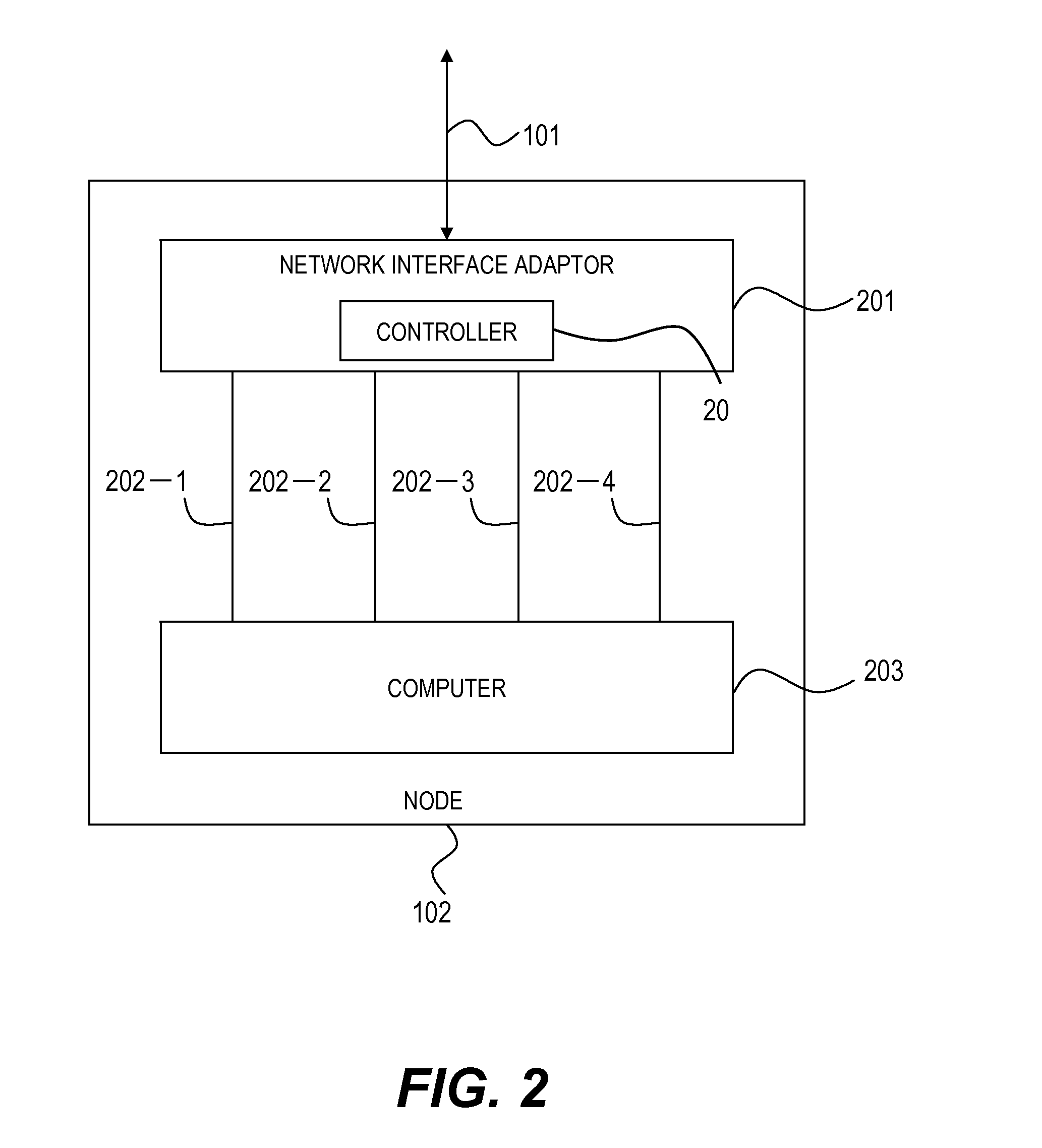
[0056]FIG. 2 illustrates an example of a configuration of the node 102. The node 102 includes a computer 203, and a network interface adaptor 201 for coupling the computer 203 to the network 100 via the link 101. The computer 203 and the network interface adaptor 201 are interconnected via at least two interfaces 202-1, 202-2, 202-3, and 202-4. FIG. 2 illustrates four interfaces. However, an arbitrary number of two or more interfaces can be dispo...

second embodiment

[0205]FIG. 23 is a block diagram illustrating an example of a configuration of a processor in a computer to which the data transfer unit of the first embodiment of this invention is coupled.

[0206]FIG. 23 is a block diagram illustrating another configuration of the processor, that is, a processor 700 used in the computer 203 illustrated in FIGS. 4 and 21.

[0207]The processor 700 includes at least one CPU core 701, a routing information storage unit 702, a main memory control unit 703, and an interconnection unit 704.

[0208]The main memory control unit 703 is coupled to the main memory via at least one memory bus 705.

[0209]The interconnection unit 704 provides at least one interconnect 706 for interconnection between processors or between a processor and an I / O hub, and is coupled to another processor or an I / O hub. Specifically, the interconnects 706 correspond to the interconnects 404-1, 404-2, 404-3, 404-4, 405-1, 405-2, 405-3, 405-4, 405-5, and 405-6 illustrated in FIG. 4, and the i...


PUM


Abstract

In order to improve throughput by suppressing contention of hardware resources in a computer to which a data transfer unit is coupled, a control unit for transferring data between a first interface coupled to the computer and a second interface coupled to a memory transaction issuing unit for issuing, when one of the first interface and the second interface receives an access request to a memory of the computer, a memory transaction for the main memory to the first interface, the first interface includes a plurality of interfaces coupled in parallel to the computer, and the control unit further includes a memory transaction distribution unit for extracting an address of the main memory, which is contained in the memory transaction issued by the memory transaction issuing unit, and selecting an interface having address designation information set therein, which corresponds to the extracted address to transmit the memory transaction.

Description

CLAIM OF PRIORITY[0001]The present application claims priority from Japanese patent application JP2008-223309 filed on Sep. 1, 2008, the content of which is hereby incorporated by reference into this application.BACKGROUND OF THE INVENTION[0002]This invention relates to an apparatus, which is coupled to a computer, for transferring data to a main memory of the computer.[0003]According to studies conducted by the inventors of this invention, in a data transfer unit which is involved in data inputting / outputting of a computer, such as a network interface adaptor, a storage interface adaptor, and a graphics adaptor, there is used direct memory access (DMA) transfer that transfers data to a main memory of the computer without using any processor. Load reduction on a processor and high speed data transfer are being attained by performing data transfer to the main memory without using any processor.[0004]The data transfer unit is generally coupled to the computer via an interface defined ...

Claims


Application Information

Patent Timeline
IPC IPC(8): G06F13/28
CPCG06F13/128
Inventor YOSHIMURA, CHIHIRONAGASAKA, YOSHIKOSUKEGAWA, NAONOBUTAKAYAMA, KOICHI
Owner HITACHI LTD
Learn More