
Cam phaser helical bias spring having a square end for retention

Active Publication Date: 2010-03-18
DELPHI TECH IP LTD
View PDF1 Cites 12 Cited by
  • Summary
  • Abstract
  • Description
  • Claims
  • Application Information

AI Technical Summary

Benefits of technology

[0013]Briefly described, a helical phaser bias spring in accordance with the present invention includes at least one linear region and an adjacent region having a radius of curvature less than that of the helix. A mating channel in the phaser receives the flat portion of the spring and adjacent region to lock the spring to the phaser at either the rotor or the stator. Preferably, the spring includes two flat regions separated by a bend of about 90°. Additional flat regions, for example three (defined herein as a “square” end to a spring) are possible, separated by right and / or other angle bends. In a phaser rotor or stator, the geometric shape required to hold a spring end having a flat is easier to form with powdered metal tooling or diecasting than is a circular, radial, or axial shape for receiving a spring tang as in the prior art, and the packaging volume required for the spring is smaller.

Problems solved by technology

A shortcoming of such prior art phasers using helical bias springs is that the shape required in the rotor and / or stator to anchor and restrain a radial or axial tang is known to cause difficulties in forming powdered metal components.
In addition, an axially bent end increases the axial length of the phaser, which is undesirable.
Further, in pulley phaser applications wherein the phaser must be sealed to prevent oil leakage to the exterior of the part, packaging is difficult because a cover plug is required for plugging the access hole for the central cam bolt.
The space required for the cover plug consumes the space otherwise usable for an axial or radial spring end.

Method used


Image

  • Cam phaser helical bias spring having a square end for retention
  • Cam phaser helical bias spring having a square end for retention
  • Cam phaser helical bias spring having a square end for retention

Examples


Embodiment Construction

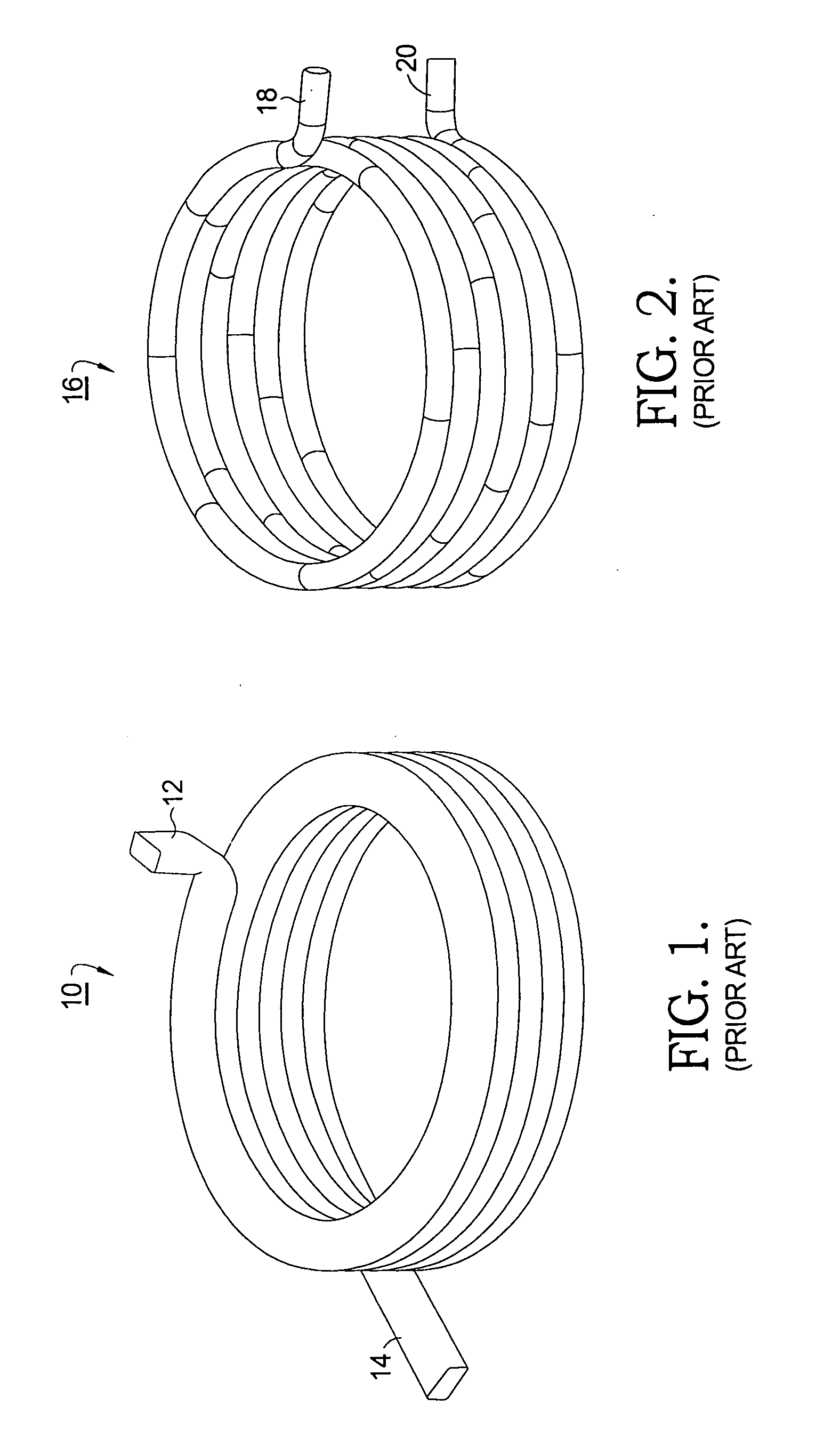
[0028]Referring to FIG. 1, a first prior art helical bias spring 10 for a phaser (not shown) includes an axial tang 12 at a first end and a tangential tang 14 at a second end. The spring stock is rectangular in cross-section.

[0029]Referring to FIG. 2, a second prior art helical bias spring 16 for a phaser includes a first radial tang 18 at a first end and a second radial tang 20 at a second end. The spring stock is round in cross-section.

[0030]Springs 10 and 16 are shown as examples of prior art springs used in prior art camshaft phasers. Note that prior art springs 10,16 employ tangs at both ends for being grounded to the stator and rotor of a phaser and further that the coils are circular and of unvarying radius.

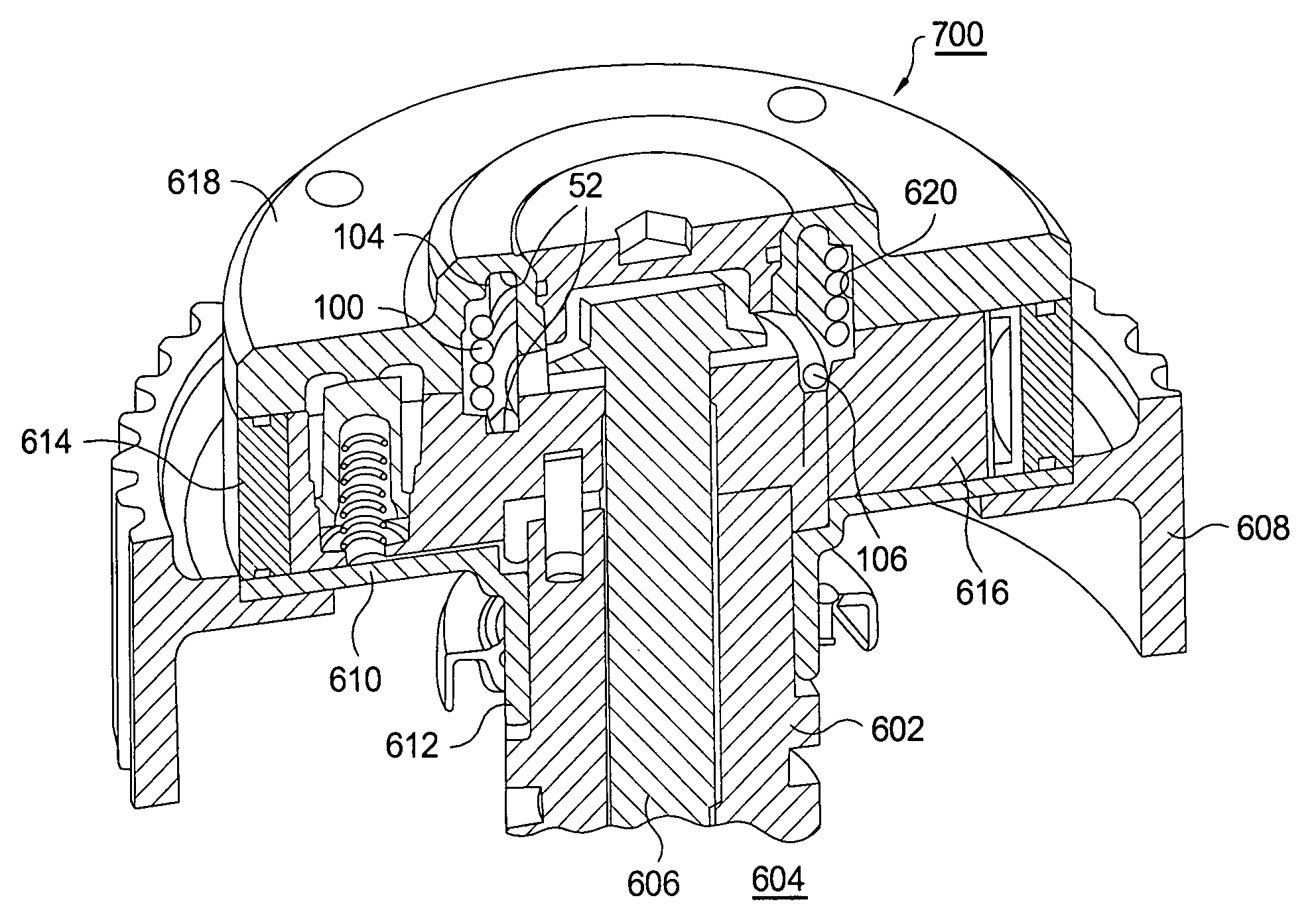
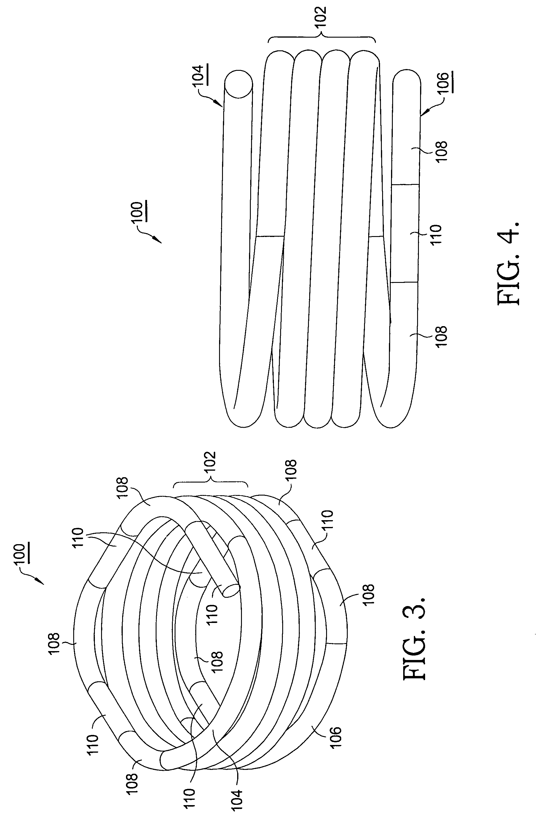
[0031]Referring to FIGS. 3 and 4, a first embodiment 100 is shown of a phaser bias spring in accordance with the present invention. Spring 100 comprises a plurality of circular coils 102 all having a first radius. At least one of end coils 104,106 has regions 108 of radius...


PUM


Abstract

A helical phaser bias spring including at least one linear region and an adjacent region having a radius of curvature less than that of the helix. A channel in the phaser receives the linear region of the spring and adjacent region to lock the spring to the phaser at either the rotor or the stator. Preferably, the spring includes two linear regions separated by a bend of about 90°. Additional linear regions are possible, separated by right and / or other angle bends. In a phaser rotor or stator, the geometric shape required to hold a spring end having a flat is easier to form with powdered metal tooling or diecasting than is a circular, radial, or axial shape for receiving a spring tang as in the prior art, the packaging volume required for the spring is smaller, and spring friction is lowered.

Description

TECHNICAL FIELD[0001]The present invention relates to phasers for varying the phase of combustion valve actuation with respect to a crankshaft in an internal combustion engine; more particularly, to such a phaser employing a spring for biasing the rotational position of a phaser rotor with respect to an associated phaser stator through at least a portion of the rotor range of authority; and most particularly, to such a phaser wherein a helical bias spring has at least one linear portion (also referred to herein as a “flat” portion) accompanied by a region of radius of curvature smaller than that of the helix at an end convolution thereof replacing a prior art radial or axial tang for engaging either the stator or the rotor.BACKGROUND OF THE INVENTION[0002]Camshaft phasers for varying the timing of combustion valves in an internal combustion engine transmit crankshaft torque to the engine camshaft, allowing varied timing of the camshaft relative to the crankshaft position.[0003]It is...

Claims


Application Information

Patent Timeline
IPC IPC(8): F01L1/34
CPCF01L2001/34483F01L1/3442
Inventor LICHTI, THOMAS H.STRANDBURG, III, ALAN G.
Owner DELPHI TECH IP LTD
Features
  • Generate Ideas
  • Intellectual Property
  • Life Sciences
  • Materials
  • Tech Scout
  • Unparalleled Data Quality
  • Higher Quality Content
  • 60% Fewer Hallucinations
Learn More