Method of manufacturing a unitary conduit for transporting fluids

a technology of fluid transporting conduits and unitary conduits, which is applied in the direction of transportation and packaging, greenhouse gas reduction, lighting and heating apparatus, etc., can solve the problems of reducing the temperature margin of engine exhaust gas, affecting the operation of turbines, and excessive fuel maldistribution within turbine engines

Active Publication Date: 2010-03-18
GENERAL ELECTRIC CO
View PDF61 Cites 39 Cited by
  • Summary
  • Abstract
  • Description
  • Claims
  • Application Information

AI Technical Summary

Problems solved by technology

Because of limited fuel pressure availability and a wide range of required fuel flow, many fuel injectors include pilot and main nozzles, with only the pilot nozzles being used during start-up, and both nozzles being used during higher power operation.
Over time, continued exposure to high temperatures during turbine engine operations may induce thermal stresses in the conduits and fuel nozzles which may damage the conduits or fuel nozzle and may adversely affect their operation.
For example, thermal stresses may cause fuel flow reductions in the conduits and may lead to excessive fuel maldistribution within the turbine engine.
Furthermore, over time, continued operation with damaged fuel nozzles may result in decreased turbine efficiency, turbine component distress, and / or reduced engine exhaust gas temperature margin.
Conventional gas turbine engine components such as, for example, fuel nozzles and their associated conduits, are generally expensive to fabricate and / or repair because the conventional fuel nozzle designs having complex conduits for transporting fuel include a complex assembly and joining of more than thirty components.
More specifically, the use of braze joints can increase the time needed to fabricate such components and can also complicate the fabrication process for any of several reasons, including: the need for an adequate region to allow for braze alloy placement; the need for minimizing unwanted braze alloy flow; the need for an acceptable inspection technique to verify braze quality; and, the necessity of having several braze alloys available in order to prevent the re-melting of previous braze joints.
Moreover, numerous braze joints may result in several braze runs, which may weaken the parent material of the component.
The presence of numerous braze joints can undesirably increase the weight and manufacturing cost of the component.

Method used


Image

  • Method of manufacturing a unitary conduit for transporting fluids
  • Method of manufacturing a unitary conduit for transporting fluids
  • Method of manufacturing a unitary conduit for transporting fluids

Examples


Embodiment Construction

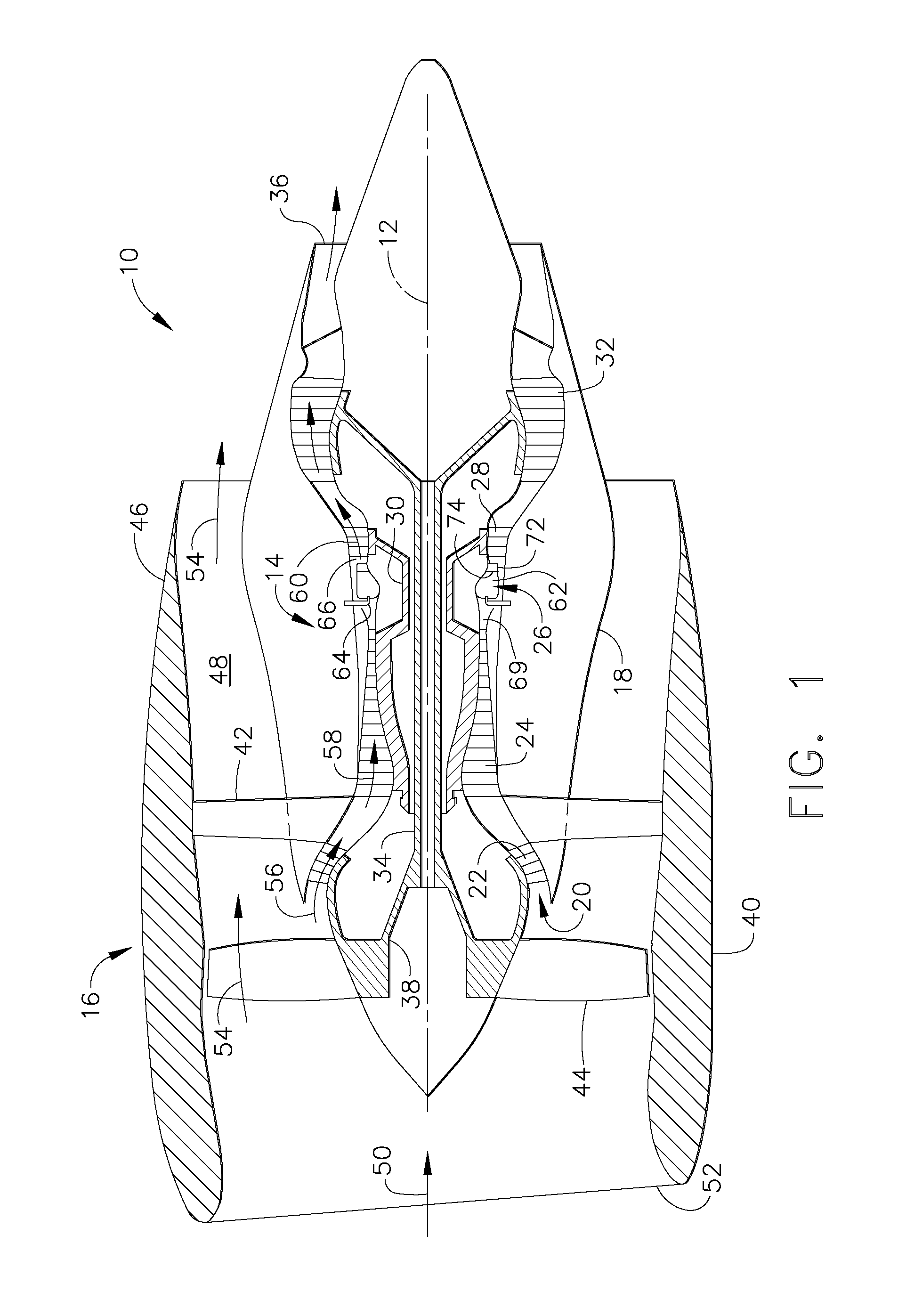
[0024]Referring now to the drawings in detail, wherein identical numerals indicate the same elements throughout the figures, FIG. 1 shows in diagrammatic form an exemplary gas turbine engine 10 (high bypass type) incorporating an exemplary embodiment of a unitary conduit for transporting liquid fuel to fuel injectors. The exemplary gas turbine engine 10 has an axial centerline axis 12 therethrough for reference purposes. Engine 10 preferably includes a core gas turbine engine generally identified by numeral 14 and a fan section 16 positioned upstream thereof. Core engine 14 typically includes a generally tubular outer casing 18 that defines an annular inlet 20. Outer casing 18 further encloses and supports a booster 22 for raising the pressure of the air that enters core engine 14 to a first pressure level. A high pressure, multi-stage, axial-flow compressor 24 receives pressurized air from booster 22 and further increases the pressure of the air. The pressurized air flows to a comb...


PUM

PropertyMeasurementUnit
particle sizeaaaaaaaaaa

Abstract

A method for fabricating a unitary conduit is disclosed the method comprising the steps of determining three-dimensional information of the unitary conduit having at least one flow passage, converting the three-dimensional information into a plurality of slices that each define a cross-sectional layer of the unitary conduit, and successively forming each layer of the unitary conduit by fusing a metallic powder using laser energy. A unitary conduit is disclosed, comprising a body and a flow passage, wherein the flow passage and the body have a unitary construction, and made by using a rapid manufacturing process.

Description

CROSS-REFERENCE TO RELATED APPLICATIONS[0001]This Application claims priority to U.S. Provisional Application Ser. No. 61 / 044,116, filed Apr. 11, 2008, which is herein incorporated by reference in its entirety.BACKGROUND OF THE INVENTION[0002]This invention relates generally to conduits for transporting fluids, and more specifically to unitary conduits for transporting fuel into fuel nozzles used in gas turbine engines.[0003]Turbine engines typically include a plurality of fuel nozzles for supplying fuel to the combustor in the engine. The fuel is introduced at the front end of a burner in a highly atomized spray from a fuel nozzle. Compressed air flows around the fuel nozzle and mixes with the fuel to form a fuel-air mixture, which is ignited by the burner. Because of limited fuel pressure availability and a wide range of required fuel flow, many fuel injectors include pilot and main nozzles, with only the pilot nozzles being used during start-up, and both nozzles being used during...

Claims


Application Information

Patent Timeline
Patent Type & Authority Applications(United States)
IPC IPC(8): F16L9/02B22F7/02
CPCB23P6/007Y10T29/49318F23D2900/00018F23D2900/14701F23R3/14F23R3/283F23R3/286F23R3/343F23R2900/00018Y02T50/675B22F2007/068B23P6/005Y10T29/49746Y10T29/4932B23P2700/13F23D2213/00F23R3/28Y10T137/265B33Y80/00Y02P10/25Y02E30/30F23C7/004F02C7/222B23P6/00F23D11/38Y02T50/60
Inventor MCMASTERS, MARIE ANNBENJAMIN, MICHAEL A.MANCINI, ALFRED
Owner GENERAL ELECTRIC CO
Why Eureka
Try Eureka