
Wind turbine generator

a wind turbine generator and wind turbine technology, applied in the direction of electric generator control, machines/engines, rotors, etc., can solve the problems of reducing the temperature of the nacelle interior that is heated, affecting the heating efficiency of the nacelle, and seized opening and closing mechanisms, etc., to achieve efficient heating of the nacelle interior

Active Publication Date: 2010-03-18
MITSUBISHI HEAVY IND LTD
View PDF5 Cites 25 Cited by
  • Summary
  • Abstract
  • Description
  • Claims
  • Application Information

AI Technical Summary

Benefits of technology

[0010]The present invention is made in consideration of the above-described circumstances, and it is an object thereof to provide a wind turbine generator in which, even at a low outside air temperature in a cold region, malfunction of the mechanism for opening and closing the ventilation port is less prone to occur, thus increasing the reliability and improving the efficiency of heating the nacelle interior.
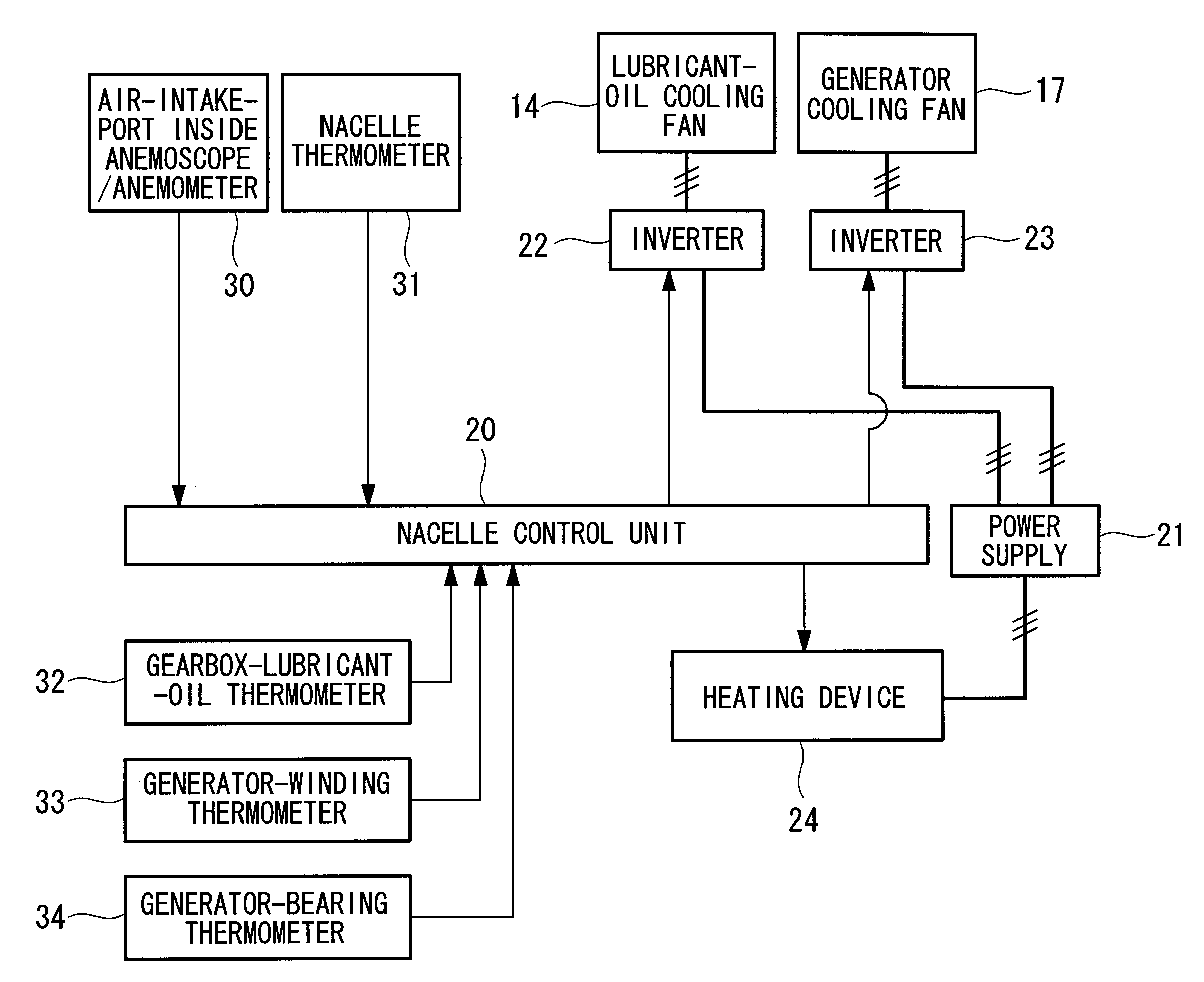
[0013]With the wind turbine generator according to the first aspect of the present invention, the ventilating fan of the cooling device can be operated with the rotating direction and the rotational speed thereof being controlled, and during the operation of the heating device, the rotating direction and the rotational speed of the ventilating fan are controlled so as to make the wind velocity at the ventilation port about zero. Therefore, even under conditions where there is a need for a heating mode in a cold-region installation environment, low-temperature outside air can be reliably prevented from flowing into the nacelle through the ventilation port without concern for seizing due to freezing or the like. That is, under conditions where there is a need for a heating mode, the wind velocity at the ventilation port is brought to about zero to create substantially the same conditions as when the ventilation port is closed.
[0014]In the wind turbine generator according to the first aspect, it is preferable that the rotating direction and the rotational speed of the ventilating fan be set by inverter control of an electric motor of the ventilating fan on the basis of measured values from wind-direction and a wind-velocity detection part for measuring the flow direction and the flow velocity of air flowing through the ventilation port. This not only makes it easy to control the operation of the ventilating fan to make the wind velocity at the ventilation port about zero but also allows fine control.
[0016]The wind turbine generator according to the second aspect of the present invention includes a bag-like inflating and deflating member disposed at the ventilation port and connected to a compressed-fluid supply part, wherein the inflating and deflating member is configured to close the ventilation port by inflation upon receiving the compressed fluid supply during the operation of the heating device and to open the ventilation port by deflation upon releasing the compressed fluid during the operation of the cooling device. Therefore, even in a cold-region installation environment, the ventilation port can reliably be opened and closed without seizing due to freezing or the like.
[0018]The wind turbine generator according to the third aspect of the present invention includes a compressed-air releasing part disposed in the vicinity of the ventilation port and connected to a compressed-fluid supply part, wherein the compressed-air releasing part is configured to close the ventilation port by means of the flow of compressed fluid released upon receiving the compressed fluid supply during the operation of the heating device. Therefore, even in a cold-region installation environment, the ventilation port can reliably be opened and closed without seizing due to freezing or the like.
[0019]According to the wind turbine generator of the present invention described above, under conditions where there is a need for a heating mode, the wind velocity at the ventilation port is brought to about zero to create substantially the same state as when the ventilation port is closed, or the ventilation port is opened and closed by means of the inflated bag-like inflating and deflating member or the flow of compressed fluid, thus eliminating a mechanical movable structural part that becomes tightly seized by freezing or the like in a cold-region installation environment. Accordingly, even at a low outside air temperature at which the nacelle interior is heated, the ventilation port is reliably closed to prevent low-temperature outside air from flowing in, thereby allowing efficient heating of the nacelle interior by means of a heater or the like.

Problems solved by technology

Therefore, a problem has been noted in that, at a low outside air temperature at which the nacelle interior is to be heated, the temperature of the nacelle interior that is heated is decreased in spite of all the efforts due to an increase in the amount of low-temperature outside air flowing through the openings of the air intake port and a ventilation port, thus exerting a negative influence on heating efficiency.
However, this has a problem in that the above-described opening and closing mechanisms become seized due to adhesion of ice and snow or freezing at a low outside air temperature in a cold region because the opening and closing mechanisms are in direct contact with outside air, which makes an opening and closing action impossible.

Method used


Image

  • Wind turbine generator
  • Wind turbine generator
  • Wind turbine generator

Examples


first embodiment

[0054]In a first embodiment, the nacelle closing mechanism which prevents or reduces entry of outside air into the nacelle 3 by controlling the rotating direction and rotational speed of a cooling ventilating fan provided at the nacelle 3 of the wind turbine generator 1 will be described.

[0055]As shown in FIG. 3, for example, the nacelle 3 accommodates a driving and generating mechanism equipped with a generator 11 that is connected to the rotor head 4 via a gearbox 10. That is, generator output power W is obtained from the generator 11 by driving the generator 11 while increasing the rotational speed of the rotor head 4 with the gearbox 10.

[0056]The above-described nacelle 3 has a ventilating and cooling device that circulates introduced outside air therethrough and thereafter exhausts it to the outside of the nacelle so as to prevent an internal temperature rise during operation.

[0057]In the configuration example of the ventilating and cooling device shown in FIG. 3, an air intake...

second embodiment

[0077]A second embodiment of the present invention will be described with reference to FIGS. 5 to 8. The same components as those in the foregoing embodiment are given the same reference numerals and detailed descriptions thereof will be omitted.

[0078]In this embodiment, a bag-like inflating and deflating member connected to a compressed-fluid supply part is provided, as a nacelle closing mechanism, at the air intake port 12, which is one of the ventilation ports. The inflating and deflating member in this case is a balloon 40, which closes the air intake port 12 by means of the balloon shape during inflation upon receiving the compressed air supplied from an intake-air shutoff compressor 41 of the compressed-fluid supply part and which opens the air intake port 12 during deflation upon releasing the compressed air.

[0079]As shown in FIGS. 7A and 7B, for example, the balloon 40 is accommodated in a cover member 40a that defines the shape during inflation. It is preferable not only th...

third embodiment

[0085]A third embodiment of the present invention will be described with reference to FIG. 9. The same components as those in the foregoing embodiments are given the same reference numerals and detailed descriptions thereof will be omitted.

[0086]In this embodiment, as a nacelle closing mechanism, the ventilation port is closed by means of the flow of compressed fluid. That is, it has a configuration and control in which the balloon 40 in the second embodiment described above is changed to an air curtain nozzle 50, in which, instead of inflating the balloon 40, compressed air is made to flow out through the air curtain nozzle 50 to form an air curtain, and instead of deflating the balloon 40, the supply of the compressed air to the air curtain is stopped.

[0087]With such a configuration and control, when the air curtain, which is a flow of compressed air, is formed, the air intake port 12 becomes closed, and when no air curtain is formed, the air intake port 12 becomes opened. Accordi...


PUM


Abstract

A wind turbine generator is provided in which the efficiency of heating the interior of a nacelle can be improved at a low outside air temperature in a cold region. The wind turbine generator includes a nacelle that accommodates a driving and generating mechanism connected to a rotor head fitted with turbine blades, wherein the nacelle is equipped with a lubricant-oil cooling fan and a generator cooling fan that ventilate the interior of the nacelle to prevent an increase in the temperature of the interior and a heating device that raises the temperature of the interior of the nacelle at a low outside air temperature, wherein the cooling fans can be operated with the rotating directions and the rotational speeds thereof being controlled, and during the operation of the heating device, the rotating directions and the rotational speeds of the cooling fans are controlled so as to make the wind velocity at the ventilation ports thereof about zero.

Description

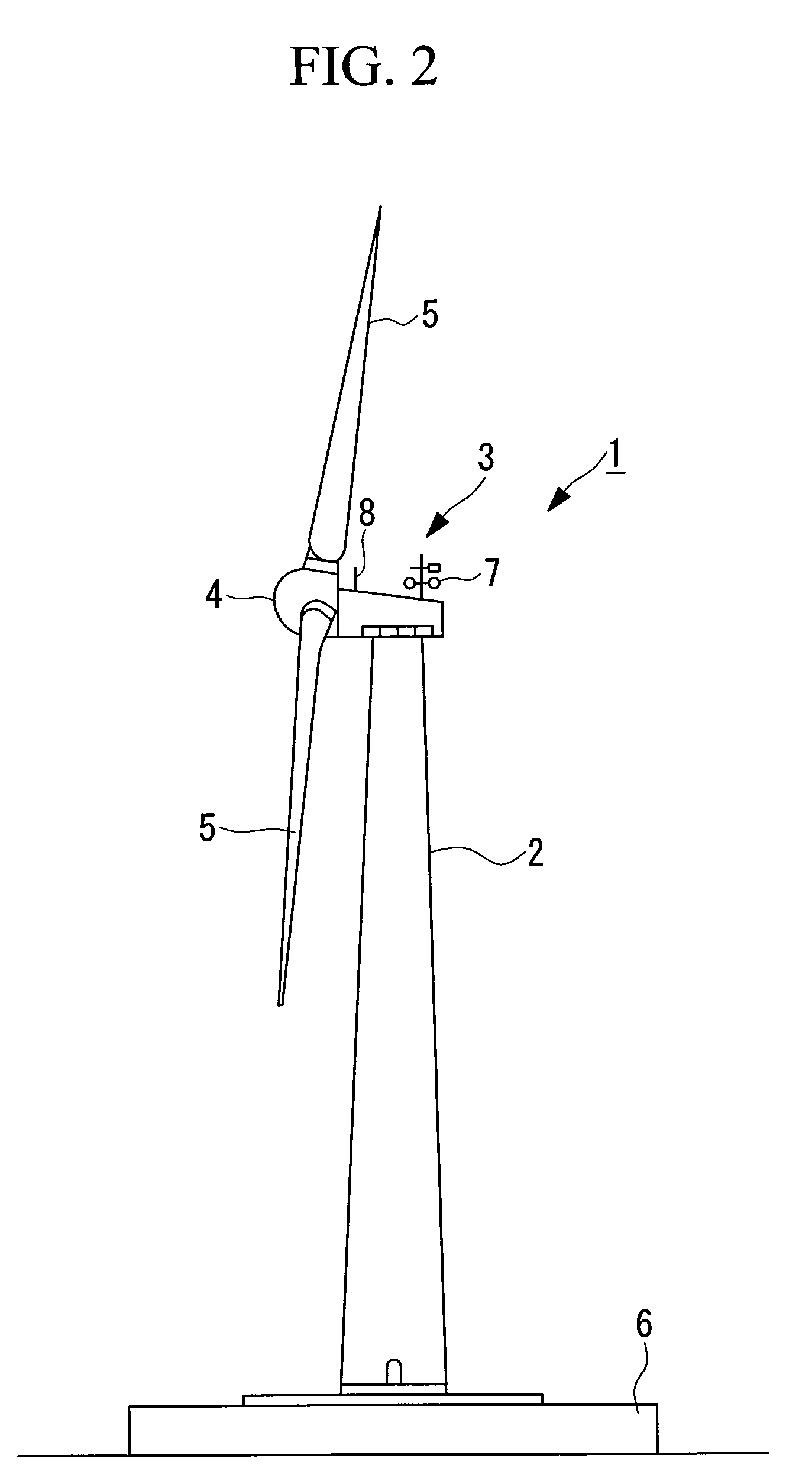
TECHNICAL FIELD[0001]The present invention relates to a wind turbine generator that generates electricity using a wind turbine that converts natural wind energy to rotational power.BACKGROUND ART[0002]A known wind turbine generator in the related art generates electricity using wind power, which is natural energy. This type of wind turbine generator is configured such that a nacelle mounted on a tower is provided with a rotor head fitted with wind turbine blades, a main shaft connected to the rotor head so as to rotate together therewith, a gearbox connected to the main shaft that rotates by receiving wind power with the wind turbine blades, and a generator driven by the shaft output power of the gearbox. In the thus-configured wind turbine generator, the rotor head having the wind turbine blades that convert wind power to rotational power and the main shaft rotate to generate shaft output power, and the shaft output power, which is increased in rotational speed through the gearbox ...

Claims


Application Information

Patent Timeline
IPC IPC(8): F03D9/00F03D7/00
CPCF03D11/00F05B2260/64Y02E10/726Y02E10/722Y02E10/725Y02E10/721F03D80/00F03D80/60F03D80/30Y02E10/72F05B2270/303F05B2260/20F05B2260/98
Inventor MATSUSHITA, TAKATOSHI
Owner MITSUBISHI HEAVY IND LTD
Learn More