Low-power relaxation oscillator

Active Publication Date: 2010-03-18
EM MICROELECTRONIC-MARIN
View PDF9 Cites 22 Cited by
  • Summary
  • Abstract
  • Description
  • Claims
  • Application Information

AI Technical Summary

Benefits of technology

[0012]An aim of the present invention is to address the disadvantages mentioned above by providing a low-power relaxation oscillator, i.e. one with a redu

Problems solved by technology

An oscillator such as that described in patent document U.S. Pat. No. 6,720,836 has the major disadvantage of having an oscillation amplitude associated with the gate-source voltage Vgs of a CMOS type transistor that can thus not be decreased in order to reduce current consumption.
Moreover, such a relaxation oscillator uses a current mirror with a size ra

Method used


Image

  • Low-power relaxation oscillator
  • Low-power relaxation oscillator
  • Low-power relaxation oscillator

Examples


Embodiment Construction

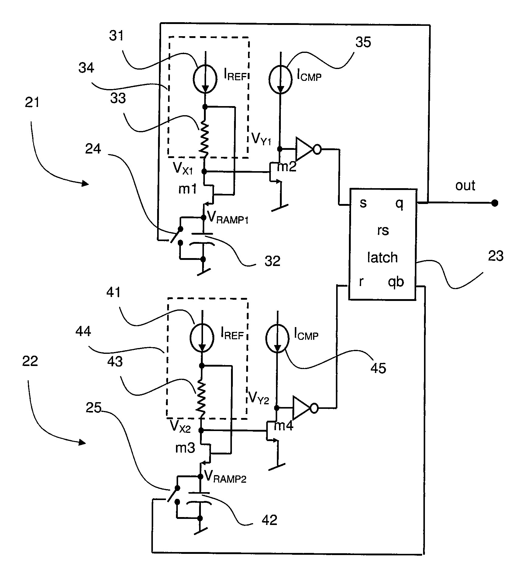
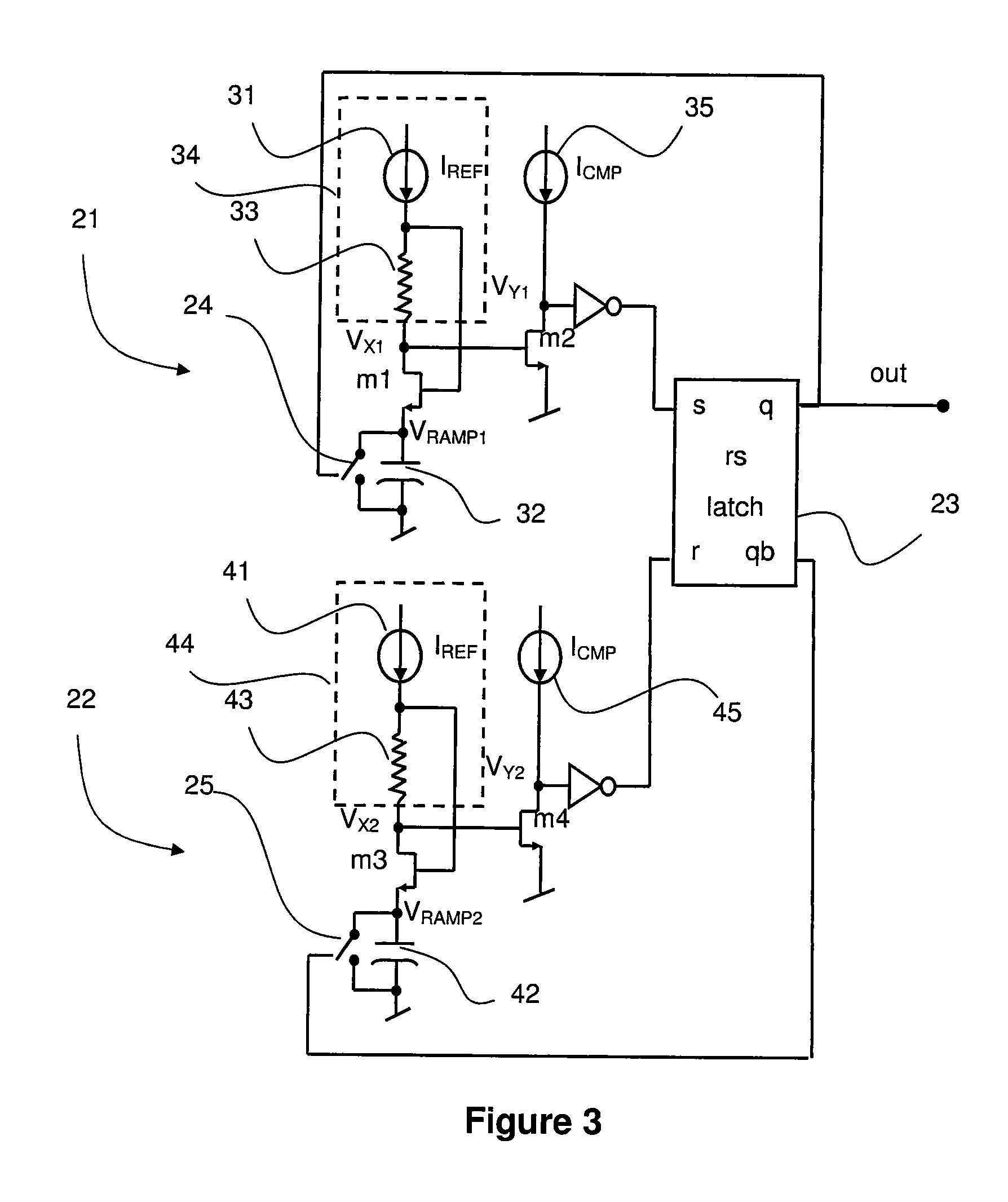
[0025]The invention will be described below solely on the basis of non-restrictive examples in association of FIGS. 3 and 4. FIG. 3 shows a low-power relaxation oscillator according to a first embodiment of the invention. The overall structure of the relaxation oscillator according to this first embodiment is still like that presented in association with the base relaxation oscillator according to the prior art. Two like modules 21, 22 are evident that each comprise a ramp generator, a generator of a reference (voltage?) and a comparator. The output of each of these two modules is then connected to the input terminals of an asynchronous flip-flop 23, the outputs of which are relooped onto the input of each of the modules. However, the present invention differs from the oscillator according to the prior art by the configuration of the modules. In particular, an advantageous combination of the ramp generator with the generator of a reference voltage and the comparator is provided in o...


PUM


Abstract

The low-power relaxation oscillator comprises a first module (21) having a ramp generator formed by a reference current source (31) and a storage capacitor (32) defining a ramp voltage (Vramp1), and a voltage comparator (m1, m2) for comparing the ramp voltage with a reference voltage, a second module (22, 41, 42, Vramp2, m3, m4) similar to the first module and an asynchronous flip-flop (23) receiving the output signal of the comparator of the first module at a first input (s) and the output signal of the comparator of the second module at a second input (r). For each module a generator of said reference voltage is configured by adding a reference resistance (33, 43) between the reference current source and the storage capacitor. Thus, the generation of the reference voltage and the ramp voltage is conducted on the very same current branch. This enables the electrical power consumption of the oscillator to be reduced.

Description

[0001]This application claims priority from European Patent Application No. 08163797.7, filed Sep. 5, 2008, the entire disclosure of which is incorporated herein by reference.TECHNICAL FIELD[0002]The invention relates in general to a relaxation oscillator used in particular in radio-frequency applications. More specifically, the invention relates to a low-power relaxation oscillator that can be integrated into a radio identification transponder (RFID).TECHNOLOGICAL BACKGROUND[0003]A relaxation oscillator is known from the prior art and its basic diagram is provided in FIG. 1. Such a relaxation oscillator comprises two like modules 1, 2, each having a ramp generator 3, 4 formed by a reference current source 5, 6 and a storage capacitor 7, 8 defining a ramp voltage (Vramp1, Vramp2), a reference voltage generator 9 and a voltage comparator 10, 11 for comparing the ramp voltage (Vramp1, Vramp2) with the reference voltage (Vref). An asynchronous RS type flip-flop 12 receives the output s...

Claims


Application Information

Patent Timeline
IPC IPC(8): H03K3/023
CPCH03K4/502H03K3/0233
Inventor MULLER, SIMON
Owner EM MICROELECTRONIC-MARIN
Why Eureka
Try Eureka