Ventilation System and Method

Inactive Publication Date: 2010-03-18
WILHELMSEN TECHN SOLUTIONS SWEDEN
View PDF11 Cites 4 Cited by
  • Summary
  • Abstract
  • Description
  • Claims
  • Application Information

AI Technical Summary

Benefits of technology

[0004]An object of the present invention is to provide a ventilation system with simple and

Problems solved by technology

As electricity passes through said resistive heat elements, some energy is lost as heat due to the resistance of said elements.
Step-wise adjustment means that the heating capacity of the resistive heater can not be continuously controlled or optimised nor accurately matched to both specific and fl

Method used


Image

  • Ventilation System and Method
  • Ventilation System and Method
  • Ventilation System and Method

Examples


Embodiment Construction

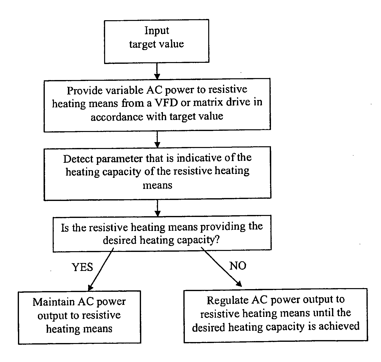
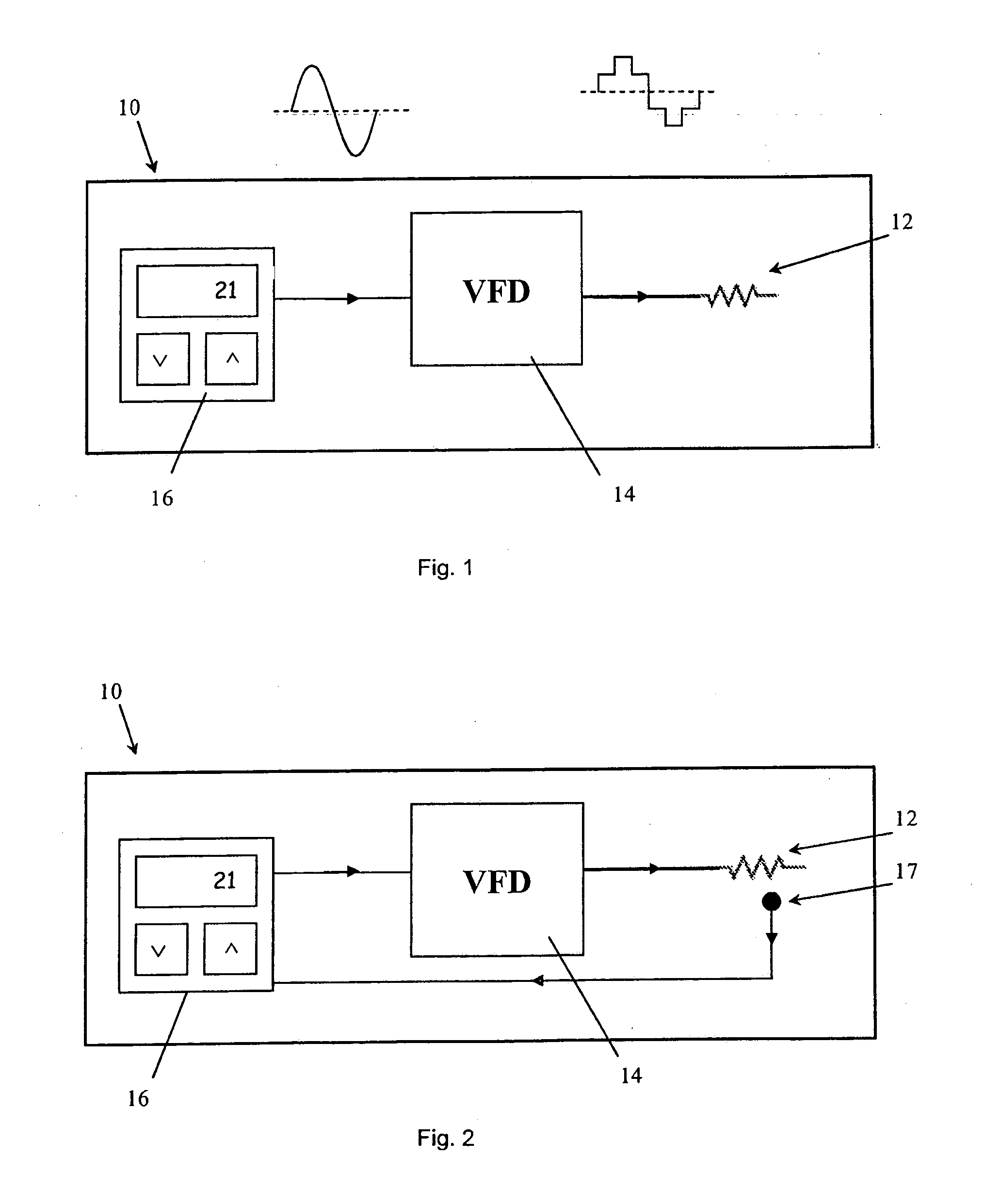
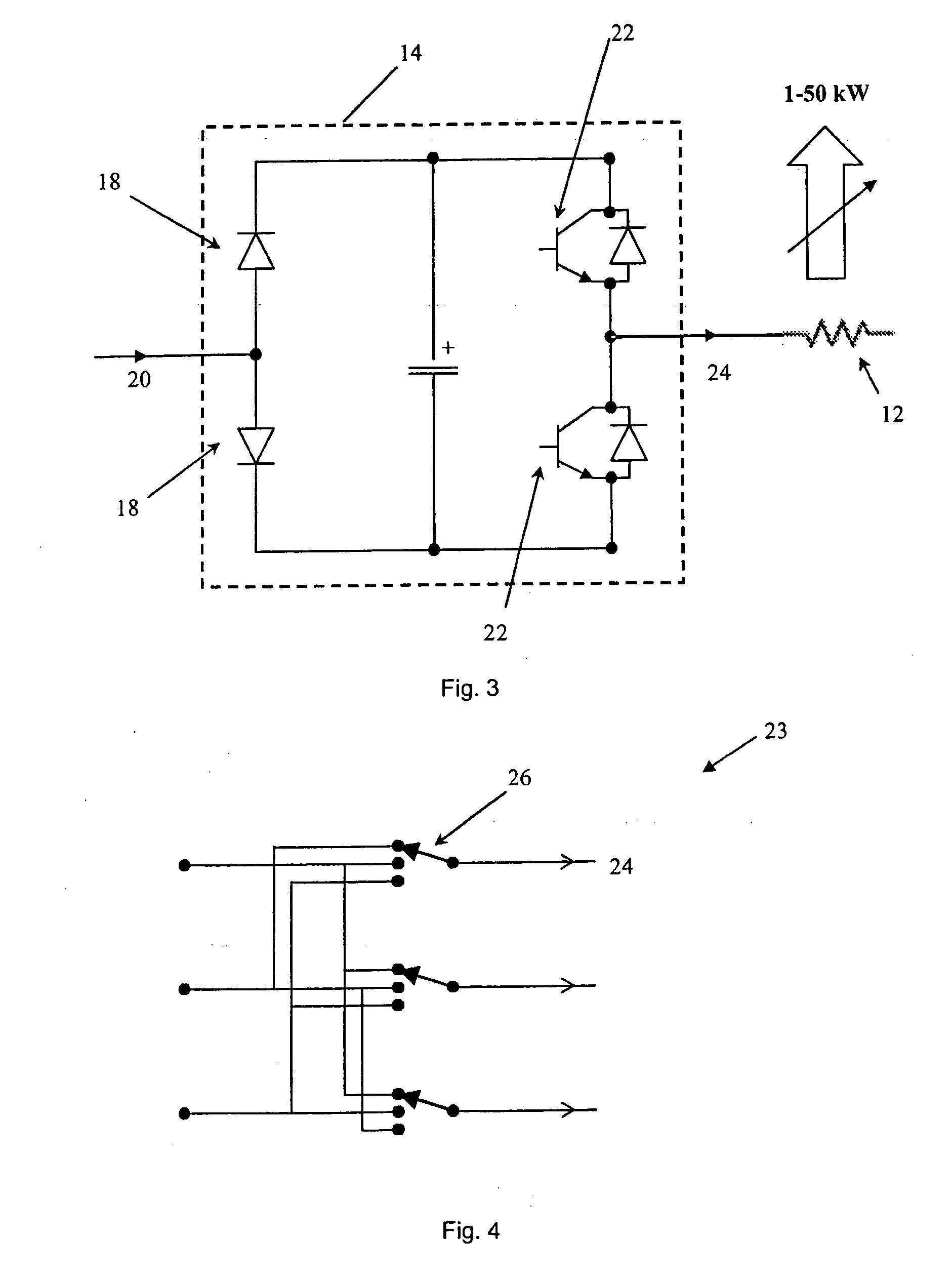
[0034]FIG. 1 shows a ventilation system 10 comprising a purely resistive heating element 12 consisting of one or more electrically conductive wires or foils located inside a stainless steel tube that heats up the supply air delivered to a cabin of a passenger ship. A VFD 14 supplies at least part of the resistive heating element 12 with electrical power and thereby controls the total heating capacity of the resistive heating element 12. A control panel on a VFD controller 16 presents various features that allow for automatic or manual control of the VFD 14 and includes display means, such as an LCD, to provide information concerning the operation of the VFD 14 and / or the resistive heating element 12.

[0035]In this example the VFD controller is provided with a target value only and not an actual value indicative of the heating capacity of the resistive heating element 12. The ventilation system 10 is calibrated so that the VFD controller supplies a pre-determined amount of power to th...


PUM


Abstract

Ventilation system (10) comprising resistive heating means (12) for heating gas flowing through the ventilation system (10) and means that are arranged to provide a 5 controlled, continuously variable AC voltage/current to at least part of the resistive heating means (12) of the ventilation system (10) to modulate the power (24) being supplied thereto and to enable continuous regulation of the temperature of gas flowing through the ventilation system (10).

Description

TECHNICAL FIELD[0001]The present invention concerns a ventilation system and a method for continuously regulating the temperature of gas flowing through a ventilation system.BACKGROUND OF THE INVENTION[0002]Ventilation systems usually comprise resistive heating elements to heat gas passing through the ventilation system. A heater usually contains one or more resistive heating elements, such as electrically conductive wires or foils, which are connected to an electrical supply (usually a mains voltage of 230-480 V, 50-60 Hz). As electricity passes through said resistive heat elements, some energy is lost as heat due to the resistance of said elements. The more current that flows through the resistive heat elements, the more heat is generated.[0003]If a resistive heater comprises a plurality of resistive heating elements, fuses and relays are used to connect different numbers of resistive heating elements in order to increase or decrease the heating capacity of the resistive heater (i...

Claims


Application Information

Patent Timeline
IPC IPC(8): H05K5/00F24F11/00
CPCF24F11/006F24H9/2071H05B1/0244F24F2221/34F24F11/30F24F11/62F24F11/0001F24F2110/12F24H15/421F24H15/395F24H15/25F24H15/281F24H15/37
Inventor HANSSON, MAGNUS
Owner WILHELMSEN TECHN SOLUTIONS SWEDEN
Why Eureka
Try Eureka