Method for the quantitative display of blood flow

a blood flow and quantitative technology, applied in the field of quantitative representation of blood flow, can solve the problems of erroneous representation of total blood flow, difficulty in recognizing tissue areas with poor blood flow or none, and movement of recording units or objects during recording

Inactive Publication Date: 2010-03-18
CARL ZEISS MEDITEC AG
View PDF13 Cites 34 Cited by
  • Summary
  • Abstract
  • Description
  • Claims
  • Application Information

AI Technical Summary

Problems solved by technology

This made it difficult to recognize if tissue areas had a poor blood flow or none at all.
The underlying problem here is that the recording unit or the object to be recorded may move during recording.
Thus, without movement compensation, the maxima

Method used


Image

  • Method for the quantitative display of blood flow
  • Method for the quantitative display of blood flow
  • Method for the quantitative display of blood flow

Examples


Embodiment Construction

[0016]The preferred embodiments of the present invention will now be described with reference to FIGS. 1-4 of the drawings. Identical elements in the various figures are designated with the same reference numerals.

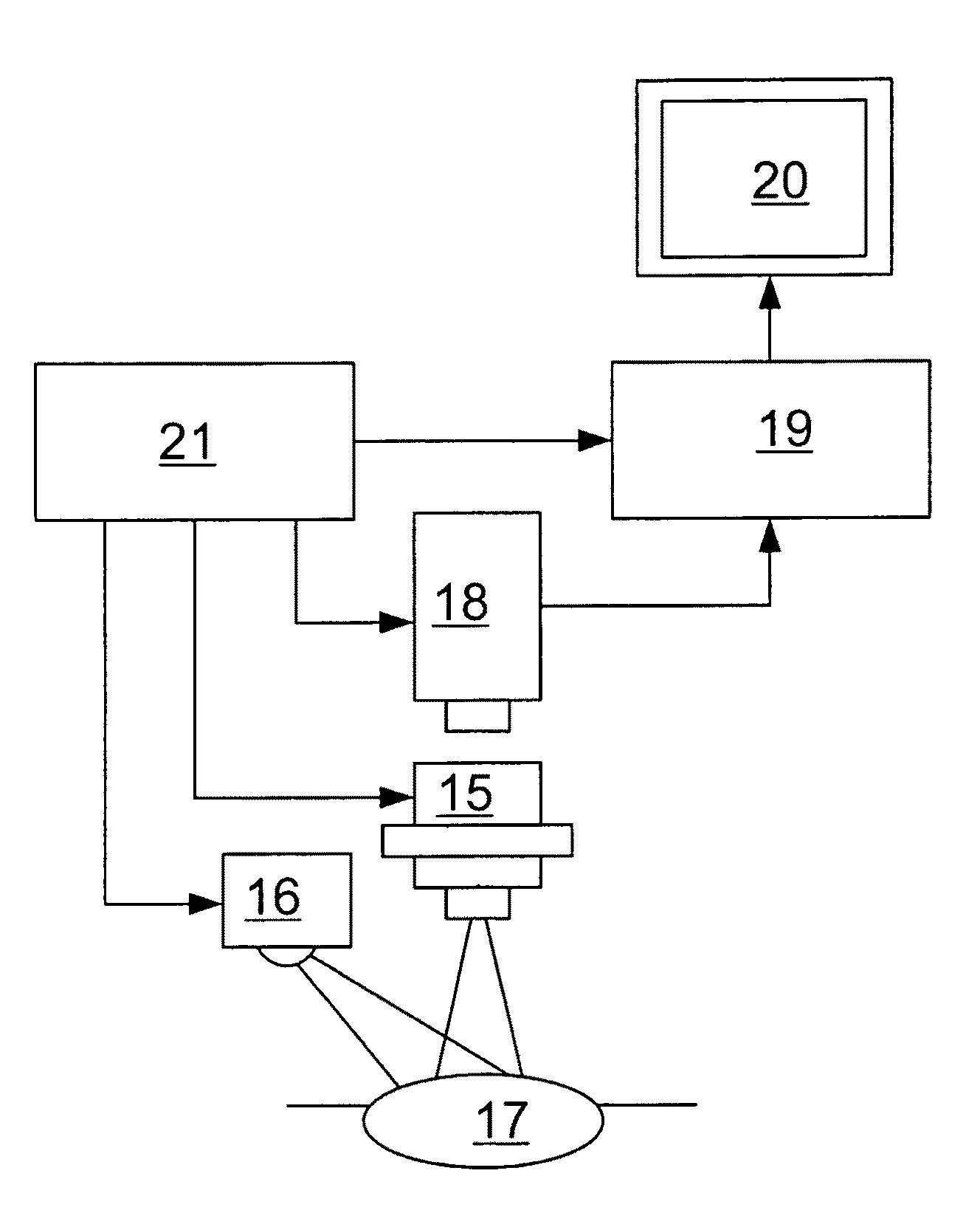
[0017]The complete system with the data flows and the individual processing steps is described in FIG. 1 and is used for presenting and evaluating the blood flow. The data are recorded using a video camera 1 in the infrared range, which is arranged at the surgical microscope—not shown—or is a component thereof. The recorded infrared videos are stored in a data memory 2 and are split into individual images 4 using a video player 3. Alternatively, it is also possible to store the images of the video camera 1 directly as individual images 4. A frequency of five frames 4 per second proved to be useful for this. They are then corrected in a single image correction step 5. In the process, the corrections for the edge drop, for the dark offset or of non-linearities of the video c...


PUM


Abstract

A method for the quantitative representation of the blood flow in a tissue or vascular region is based on the signal of a contrast agent injected into the blood. Several individual images of the signal emitted by the tissue or vascular region are recorded and stored at successive points in time. For image areas of the individual images, the respective intensities of different points in time are compared and the maximum intensities of the signals are determined for these image areas. The maximum intensities are represented for these image areas.

Description

BACKGROUND OF THE INVENTION[0001]The invention relates to a method for the quantitative representation of the blood flow in a patient.[0002]Several methods for observing and determining the blood flow in tissue and vascular regions are known in which a chromophore such as indocyanine green, for example, is applied. The fluorescent dye can be observed as it spreads in the tissue or along the blood vessels using a video camera. Depending on the area of application, the observation can be non-invasive or in the course of surgery, for example via the camera of a surgical microscope.[0003]Many methods are known, where only the relative distribution of the fluorescent dye in the tissue or in the blood vessels is examined qualitatively in order to draw conclusions concerning their blood flow. For example, conclusions are made about the blood flow and diagnoses are provided by watching an IR video recorded during surgery. It is also known to record an increase in the brightness of the fluor...

Claims


Application Information

Patent Timeline
IPC IPC(8): A61B6/00G06K9/00
CPCA61B5/0261A61B5/0275A61B5/7207G06T2207/30104G06T7/0028G06T2207/10056G06T2207/10064G06T5/50G06T7/33
Inventor SCHUHRKE, THOMASMECKES, GUENTERSTEFFEN, JOACHIMMIESNER, HANS-JOACHIMRUDOLPH, FRANKNAHM, WERNER
Owner CARL ZEISS MEDITEC AG
Why Eureka
Try Eureka