Heating and cooling system using compressed fluid

a heat-transfer fluid and compressed technology, applied in ventilation systems, instruments, static/dynamic balance measurement, etc., can solve the problems of increasing the carbon footprint of the system, reducing the efficiency of the system, so as to achieve the effect of environmental protection and energy-saving

Inactive Publication Date: 2010-03-18
AIR ENERGY SOLUTIONS
View PDF24 Cites 27 Cited by
  • Summary
  • Abstract
  • Description
  • Claims
  • Application Information

AI Technical Summary

Benefits of technology

[0015]Using compressed air as a heat transport / transfer medium, and employing appropriate thermal design, embodiments of the present invention provide a temperature control mechanism that is both environment-friendly and energy-efficient. Embodiments of the present invention may use compressed air or other environmentally benign compressible fluids as a heat transport / transfer medium.

Problems solved by technology

Commonly used heat transfer fluids, such as, Freon, are not considered “green” or environmentally friendly.
Though the heat transfer fluid does not get released inside the building, procurement and disposal of a non-green fluid adds to the carbon footprint of a system.
Also, some amount of heat-transfer fluid may leak out from a closed loop to get mixed with the main air flow.
If direct heating or cooling of a flow of air is adopted to avoid the use of a heat transfer fluid, then a relatively longer time and larger consumption of energy may be needed to achieve a target temperature.
This adds to the operational cost and infrastructural requirements of the system.
Electric-only heating and / or cooling systems do not rely on fossil fuels, but usually consume a large amount of electricity to generate or extract thermal energy, resulting in a high operational cost.
The total carbon footprint of electric-only heating / cooling may be quite high, as most of the electric power plants still use fossil fuel to generate electricity.

Method used


Image

  • Heating and cooling system using compressed fluid
  • Heating and cooling system using compressed fluid
  • Heating and cooling system using compressed fluid

Examples


example implementations

1. Overall Household Heating / Cooling

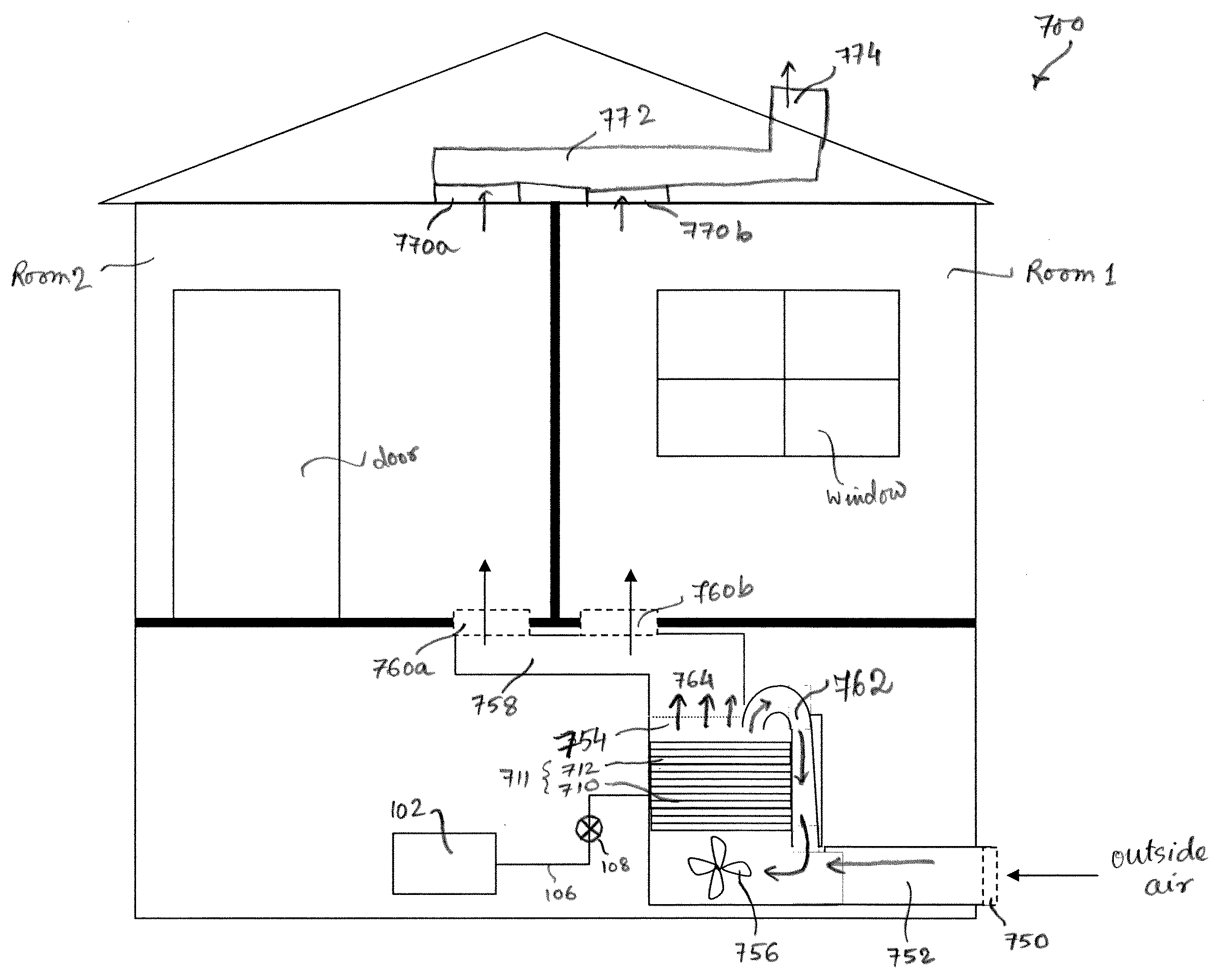
[0049]FIG. 7 shows a typical building with multiple rooms, in which an exemplary embodiment of the present invention is installed as a central temperature control system 700 akin to a HVAC system. System 700 takes in outside air that passes through a filter 750 into an entry duct 752. Entry duct 752 is coupled to a main duct 754 in which a temperature conditioning device 711 is installed. Temperature conditioning device 711 comprises one or more stages of heat tubes / vortex tubes 710 and heat exchanger mass 712. A fan or a blower 756 is configured to adjust the flow of air over the heat exchanger mass 712, including the flow of outside air. For example, when fan / blower 756 runs at a higher speed, more outside air is taken in and is made to flow over heat exchanger mass 712. Compressed air is fed to heat tube / vortex tube 710. As the compressed air passes through the heat tubes / vortex tubes 710, its thermal energy is actively controlled based on a si...


PUM


Abstract

Use of compressed air for indoor ambient temperature conditioning is disclosed. Thermal energy is imparted to or extracted from a quantity of compressed air, and the compressed air is then directed to be released inside a structure enclosing a space, whose ambient temperature needs to be controlled. Thus, the compressed air may be used as a direct heat conduction/extraction medium. A flow of external air is created over a heat exchanger mass (a “heating mass” or a “cooling mass”), so that thermal energy of the compressed air flowing inside the heat exchanger mass is transferred to the external flow of air flowing outside the heat exchanger mass. Thus, in addition to being a direct heat conduction/extraction medium, the compressed air is being used as a heat transfer medium, that ultimately gets mixed with the flow of external air. A fresh supply of external air may be used rather than using re-circulated air, in order to maintain a high quality of breathable air. A local feedback loop may be used to route back a portion of temperature-conditioned air produced by a system according to the present invention, to regulate a flow of external air over a heat exchanger mass. Other types of environmentally benign compressible fluids may be used as a heat transport/transfer fluid instead of compressed air.

Description

CROSS REFERENCE TO RELATED APPLICATIONS[0001]This application claims the benefit of U.S. Provisional Application No. 61 / 192,148, filed Sep. 16, 2008, entitled “Compressed Air HVAC System,” and U.S. Provisional Application No. 61 / 156,001, filed Feb. 27, 2009, entitled “Compressed Air Heating and Cooling System,” both of which in their entirety are hereby incorporated by reference.BACKGROUND[0002]1. Field of the Invention[0003]This invention relates generally to systems and methods for conditioning temperature of an enclosed space using a compressed fluid as a thermal energy transport and / or transfer medium.[0004]2. Related Arts[0005]In a conventional system for indoor climate control, such as, a Heating, Ventilating and Air Conditioning (HVAC) system, or a heat pump system, a network of air ducts are built into the walls / ceiling / floor of a building to circulate and / or re-circulate air inside the building. The network of air ducts is coupled to a furnace and / or a heat extraction unit,...

Claims


Application Information

Patent Timeline
Patent Type & Authority Applications(United States)
IPC IPC(8): G05B15/00F24F7/00F25B9/02
CPCF24F5/0085F25B9/004Y02E60/142F28C3/06F28D20/0034F25B9/04Y02E60/14
Inventor MIRPOURIAN, SEYED HADIGALL, PETER JAMES
Owner AIR ENERGY SOLUTIONS
Why Eureka
Try Eureka