
"plants processor and crop heads separator device for combine harvesters"

Inactive Publication Date: 2010-03-25
DEL BLANCO RAFAEL ALEJANDRO +1
View PDF12 Cites 9 Cited by
  • Summary
  • Abstract
  • Description
  • Claims
  • Application Information

AI Technical Summary

Benefits of technology

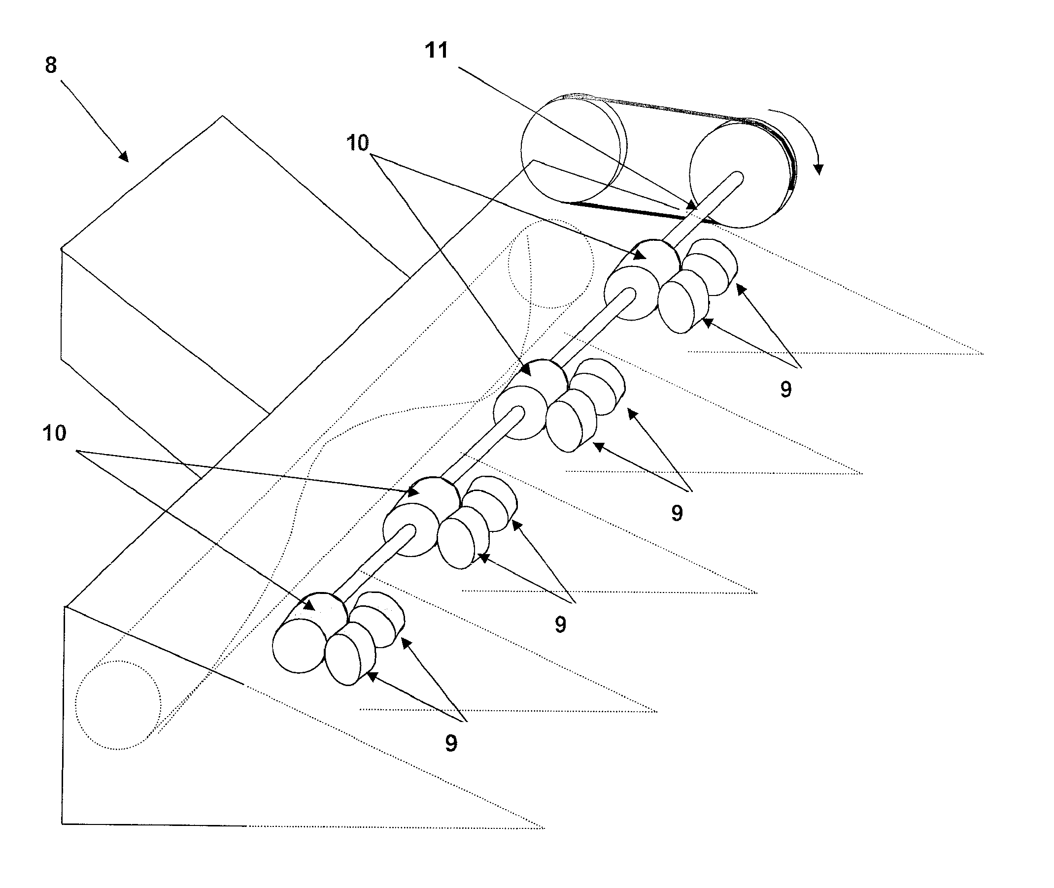
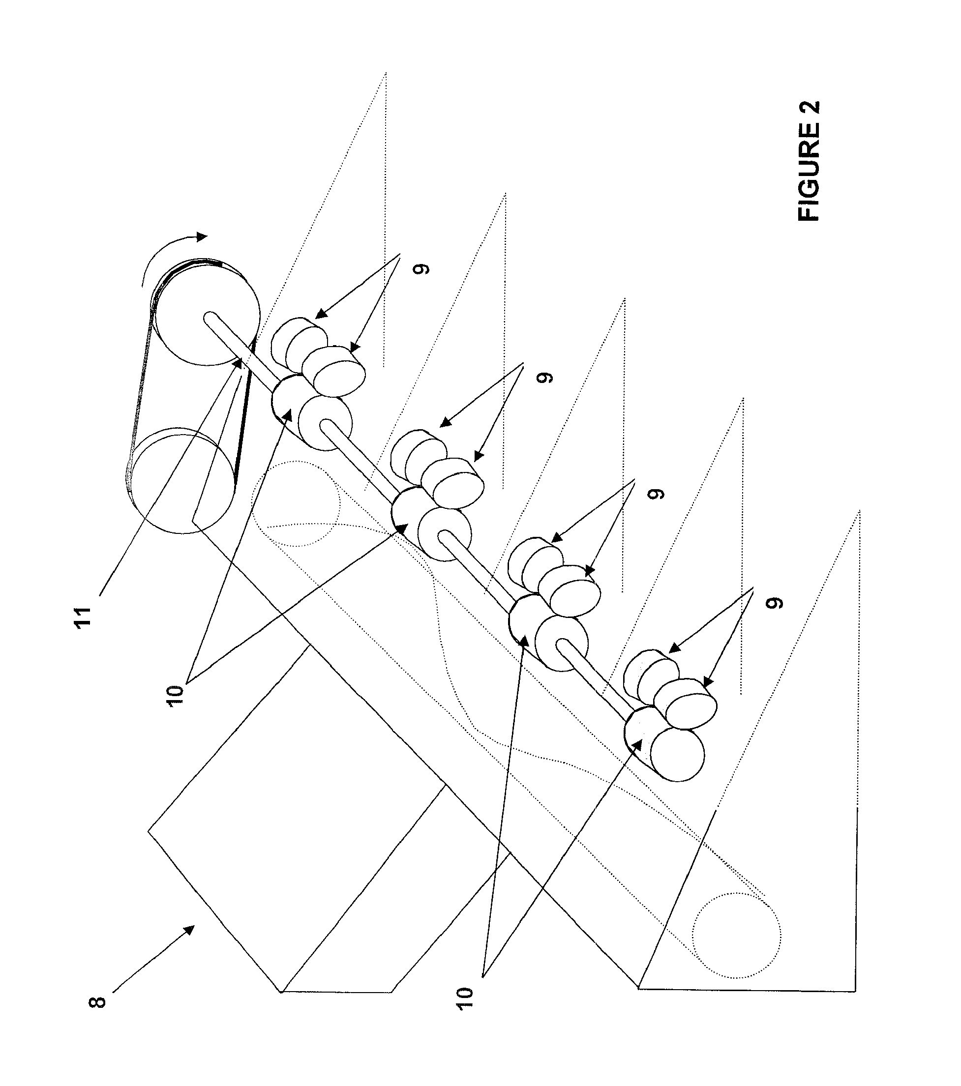
[0007]The lateral rolls with gear-like teeth, flutes or drivers, overlap those teeth, flutes or drivers edges in a synchronized fashion, they are cylindrical or rectangular in the rear end, mainly tapered with helical flightings all along or in the front end. These helical flightings are capable of taking in the plant between the rolls and thus facilitating the flow among them. Some lateral rolls systems feature stripper plates to protect the ears from the aggressiveness of the rolls.
[0054]All these advantages allow corn headers to be built with few moving parts, lighter weight, low maintenance cost, greater harvest speed and reduced grain loss.BRIEF DESCRIPTION OF FIGURES

Problems solved by technology

This study informs that if there is an excessive ground speed, the corn header will pull the ears off the stalk in the rear part of the stripper plates, piling up several ears at the same time and causing some to fall in front of the header and others to suffer loss of seeds.
If these two factors are uniform in the crop, the header adjustment is simple, but if any of these two factors are not uniform in the row, the stripper plates adjustment will not be a simple matter to solve.
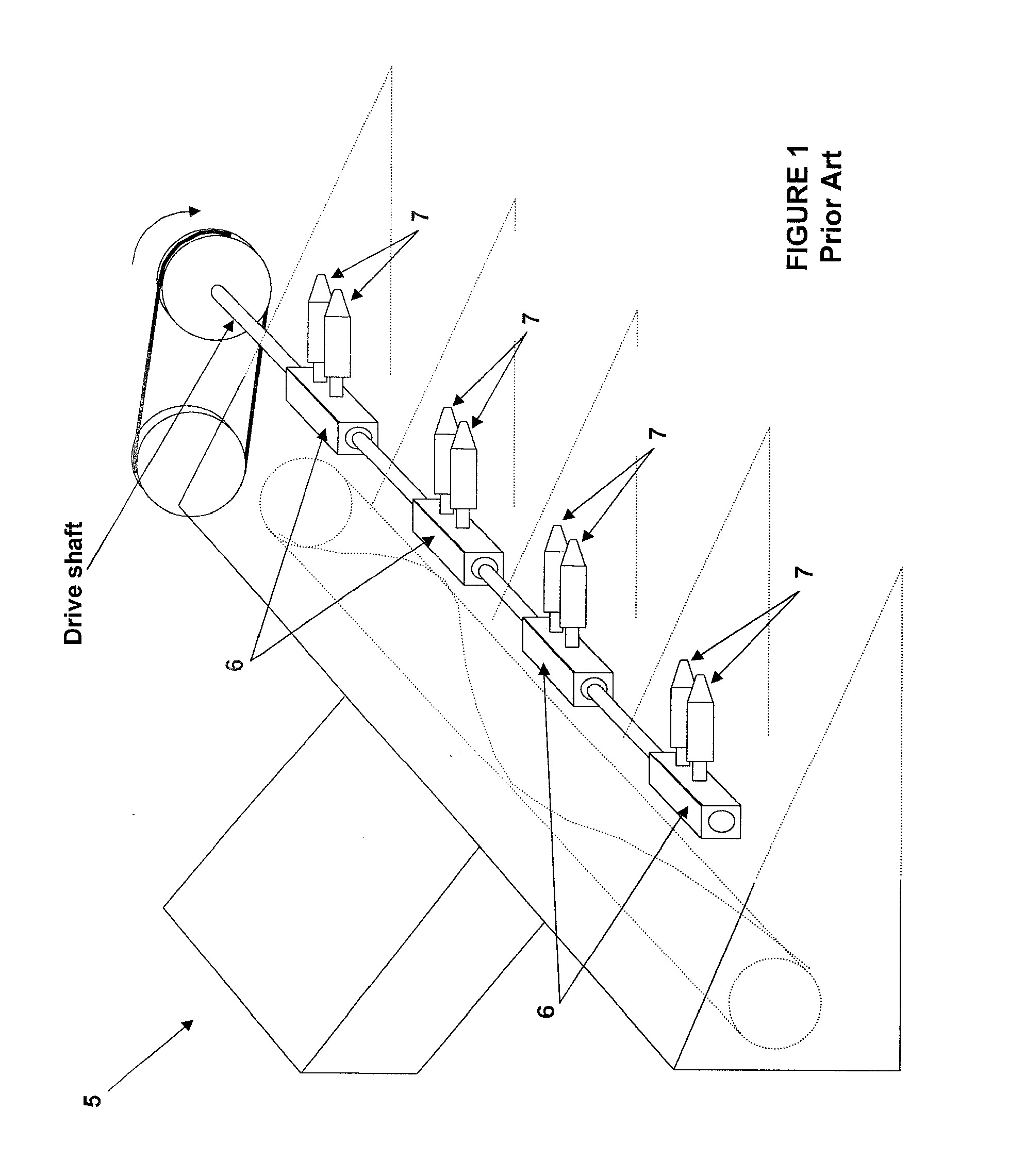
The whole kit has a high cost and a considerable weight, which, in headers with large amounts of rows, causes problems at the structural level and stability of the combine harvester.
Synchrony failures can produce contact between rolls, breakage, premature wear, stalk cuts and jamming, among others.
The issues related to the conic ends are associated with the operational area and the building area, the latter has to do, first with the fact that when the roll is not a single-piece cast, the conic ends with the helical flightings are pieces separated from the roll body, that must be cast or forged and then assembled to the roll body by welding or threading.
The operational area presents many issues.
If the helical flighting is too high, it does not allow an adequate incoming of the stalk by “pushing it”, this also takes places if the passage is narrow or if the helical flightings of one roll are not properly out-of-phase from the helical flightings of its adjacent roll, which may cause them to come into contact or close enough to cause stalk cut or incoming difficulty.
The former must have little aggressive traction surfaces with rounded edges or teeth so that they do not “bite” or hurt the ear causing seed loss making them prone to wearing, which, when it takes place, considerably decreases the traction effect, and thus the ears do not separate appropriately from the stalk being then beaten by the gathering chains and thus producing seed loss and stalk breakage that is sent to the inside of the combine harvester.
For this reason, in order to assure traction, the aggressiveness of the rolls is increased using mainly high-wing intercrossed drivers, which makes them less prone to wearing but does not allow contact between the ear and the rolls surface since it would probably mutilate it instead of separating them, pulling it downwards.
This may be problematic due to different stalks and ear sizes, which forces to constant adjustment of the stripper plate edges distance since when they are too far apart, they would not have a good grip of the ears and can this to pass through, and when too tight, the stalks would get stuck with consequences over the pushing of the plants (stalk cuts and breakage).
This hinders the performance of gathering chains and row divider points to enter the plants into the system, producing a shearing effect between the gathering chains and the plants thus causing ear loss due to their downfall or to greater amount of material to be processed by the combine harvester.
In the lateral rolls system there is a blind spot at the rear end where the material that has not been pulled by these may pile up, causing jamming, which must be withdrawn manually resulting in a loss of time.
The lateral rolls system operate in a synchronized manner, a loss of synchrony would cause contact of the flutes or drivers edges or helical flightings, causing serious damage to the system thereby requiring adjustments in precision and 90° gearboxes for its correct operation.
In a pair of lateral rolls, the rotation between rolls is opposite, this implies that the helical flightings must be left-hand helical flightings and right-hand helical flightings and also the rolls must be left-hand rolls and right-hand rolls, thereby increasing the cost of manufacturing and spare parts.

Method used


Image

  • "plants processor and crop heads separator device for combine harvesters"
  • "plants processor and crop heads separator device for combine harvesters"
  • "plants processor and crop heads separator device for combine harvesters"

Examples


Embodiment Construction

[0080]In order to explain the transverse roll operational principle, FIG. 13 shows the way as a normal transverse roll moves over a corn plant.

[0081]In the detailed operational description, of the one-roll configuration the sequence shows how the plant with the crop heads 60, it bends and moves underneath the roll 61 with no difficulties and without causing the roll 61 to drag over the plant 60. In the sequence of FIG. 14, the transverse roll 62 is assembled, in its upper part, with a set of stripper plates 63, the distance between the edges 64 of the stripper plates 63 allows the plant 65 but not the crop heads 66 to pass through.

[0082]The operational sequence of FIG. 14 is the following:

[0083]The plant 65 enters the system by passing through the stripper plates 63 without any hindrances until it comes in contact with the transverse roll 62.

[0084]In this moment begins the traction of the plant 65 towards the ground between the stripper plates 63 due to the rotation and the pressing...


PUM


Abstract

Plants processor and crop heads separator device for combine harvesters, preferably applicable in corn and sunflower crops, and adaptable to row crop harvesting headers currently under use, composed by at least one roll with its rotational axis positioned in angle as regards the forward movement of the header. This device is applicable to combine harvesters equipped with a row crop harvesting header with gathering zones, each of which has one, two, three or more rotating rolls and with a special feature as the rotational axes of the said rolls positioned in angle as regards the forward movement of the combine harvester and where at least one of them rotates opposite to the forward movement of the combine harvester.

Description

FIELD OF APPLICATION[0001]The present invention refers to a plants processor and crop head separator device for combine harvesters, preferably applicable in corn and sunflower crops, and adaptable to corn headers currently under use, this device is composed by at least one roll with its rotational axis positioned in angle as regards the forward movement of the header.PRIOR ART AND ADVANTAGES OF THE INVENTION COMPARED TO IT[0002]It is widely known that crop heads harvesting involves the following stages as basic principles: stage a) processing the plants, that is exploring the whole plant in search for crop heads, leaving the plant on the ground in optimal conditions for their integration with the soil, avoiding the entry of material that is not part of the crop heads to its processing systems (stalks, leaves, weeds, etc.); stage b) separating the crop head from the other parts of the plant; and finally stage c) gathering the crop head.[0003]In the present specifications, there will ...

Claims


Application Information

Patent Timeline
IPC IPC(8): A01D45/02
CPCA01D45/025A01D41/147
Inventor POEYLAUT, JOSE LUIS
Owner DEL BLANCO RAFAEL ALEJANDRO
Learn More