Hydraulic Drive Type Partial Inter-Tube Lancing System for Cleaning Steam Generator in Nuclear Power Plant

a technology of steam generator and intertube, which is applied in the direction of cleaning using liquids, greenhouse gas reduction, nuclear elements, etc., can solve the problems of reduced heat output efficiency, sludge deposited on the lower layer tube sheet of steam generator, and secondary system tube wear, etc., to achieve enhanced cleaning efficiency, reduce operating time, and increase length

a technology of steam generator and intertube, which is applied in the direction of cleaning using liquids, greenhouse gas reduction, nuclear elements, etc., can solve the problems of reduced heat output efficiency, sludge deposited on the lower layer tube sheet of steam generator, and secondary system tube wear, etc., to achieve enhanced cleaning efficiency, reduce operating time, and increase length

US20100071734A1Active Publication Date: 2010-03-25KOREA HYDRO & NUCLEAR POWER CO LTD

Image

  • Hydraulic Drive Type Partial Inter-Tube Lancing System for Cleaning Steam Generator in Nuclear Power Plant
  • Hydraulic Drive Type Partial Inter-Tube Lancing System for Cleaning Steam Generator in Nuclear Power Plant
  • Hydraulic Drive Type Partial Inter-Tube Lancing System for Cleaning Steam Generator in Nuclear Power Plant

Examples


Embodiment Construction

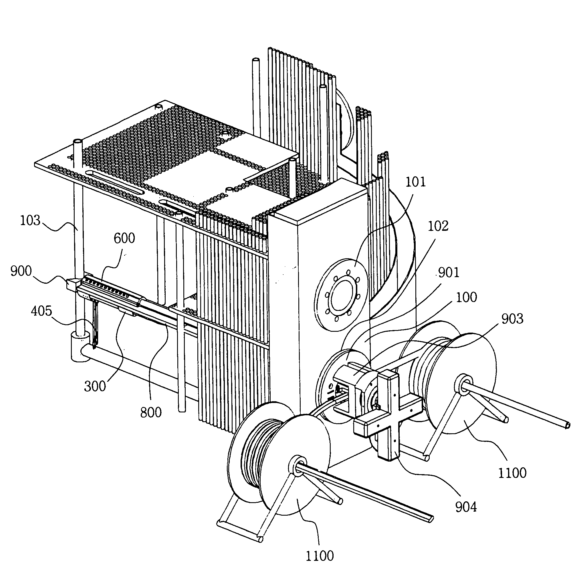
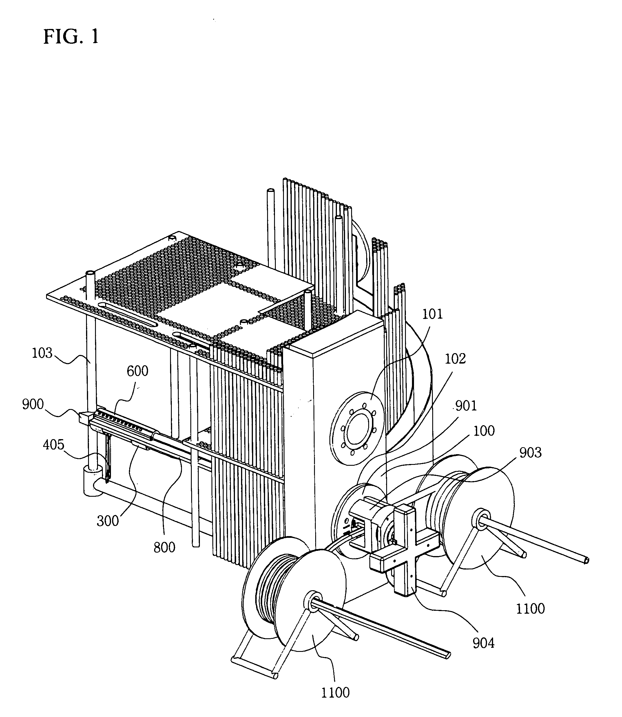
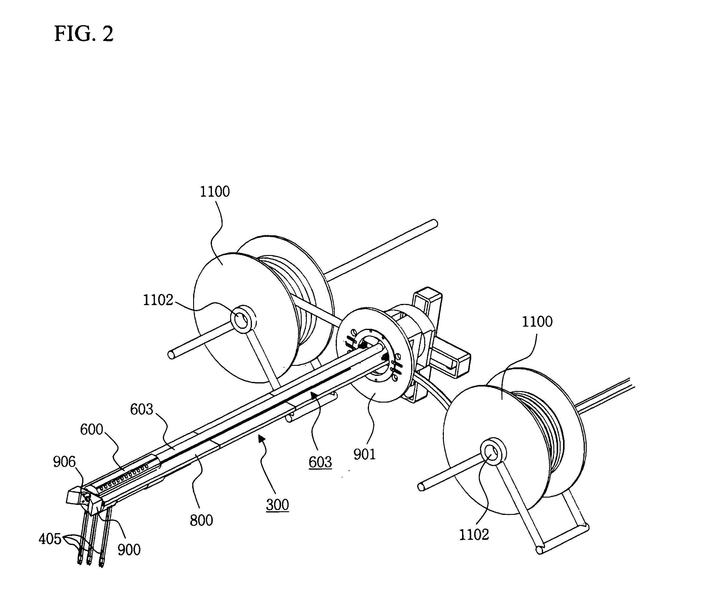
[0028]A hydraulic drive type partial inter-tube lancing system for cleaning a steam generator in a nuclear power plant according to the present invention comprises: as main components, a lancing robot 300 having elongated lances 301 of a small-diameter and long-length; a barrel spray 600 formed with a plurality of nozzles 601 to achieve a high ejection capability; a rail 800 having a crescent-shaped slot 804; a transfer strip 701 having a crescent-shaped cross section, the transfer strip 701 being wound and stored in a strip scroll box 1005; rear and front rail supporters 900 and 903 using bearings; a hand-hole flange 901 to mount the hydraulic drive type partial inter-tube lancing system at a hand-hole 102 of the steam generator; a driving device 1000 to enable twisting rotation and rectilinear reciprocating movements of the lancing robot 300 and barrel spray 600; and cable handling devices 1100 to prevent any inference with movements of the hydraulic drive type partial inter-tube ...


PUM


Abstract

A hydraulic drive type partial inter-tube lancing system for cleaning a steam generator in a nuclear power plant, which removes foreign matter, such as sludge, deposited around heat transfer tubes in the steam generator, is disclosed. More particularly, a hydraulic drive type partial inter-tube lancing system, which serves to clean a steam generator of a light-water reactor in a nuclear power plant by removing sludge, attached inside the steam generator, using high-pressure water, is disclosed.

Description

BACKGROUND OF THE INVENTION[0001]1. Field of the Invention[0002]The present invention relates to a hydraulic drive type partial inter-tube lancing system for cleaning a steam generator in a nuclear power plant, which can remove foreign matter, such as sludge, deposited around heat transfer tubes in the steam generator, and more particularly, to a hydraulic drive type partial inter-tube lancing system, which serves to clean a steam generator of a light-water reactor in a nuclear power plant by removing sludge, attached inside the steam generator, using high-pressure water.[0003]2. Description of the Related Art[0004]Generally, a steam generator provided in a nuclear power plant is a very important structure, wherein primary cooling water, to which heat energy generated from a reactor is transferred, and secondary cooling water meet each other and undergo heat exchange on the boundary of heat transfer tubes in the steam generator.[0005]As a turbine is operated by steam, generated via ...

Claims


Application Information

Patent Timeline
25 Mar 2010
Publication
US20100071734A1
IPC
B08B9/027; B08B9/04
CPC
F22B37/005; F28G15/04; F28G3/166; Y02E30/30; G21C19/307; G21C19/02
Inventors
KIM, SEOK TAE; JEONG, WOO TAE