Image display device and position detecting method

a technology of image display device and position detection, which is applied in the direction of picture reproducers using projection devices, television systems, instruments, etc., can solve the problems of low operability, inability to accurately detect the position of the laser pointer included in the reflection light from the screen, and the light output of the laser pointer accidentally entering the eye. , to achieve the effect of accurate detection of the position

Inactive Publication Date: 2010-03-25
SONY CORP
View PDF4 Cites 10 Cited by
  • Summary
  • Abstract
  • Description
  • Claims
  • Application Information

AI Technical Summary

Benefits of technology

[0009]It is therefore desirable to provide an image display device and a position detecting method capable of accurately detecting a position on an image pointed out with a laser pointer, a pointing stick, a finger, or the like, regardless of an external factor.

Problems solved by technology

However, in the methods disclosed in JP2001-109577A, JP-H05-22436A and JP2001-290600A, there is a case that light of the laser pointer included in the reflection light from the screen cannot be extracted well by the optical filter, due to wavelength fluctuations at the time of reflection at the screen.
Therefore, the position on the screen irradiated with the light, output from the laser pointer and having the wavelength out of the visible region, cannot be figured out, so that operability is low.
Further, the light having the wavelength out of the visible region is invisible, and thus there is a danger that the light output from the laser pointer accidentally enters the eye.
Also, in the method disclosed in JP2003-173236A, only the shift of the light spot in the screen is known, so that accuracy and resolution are low.

Method used


Image

  • Image display device and position detecting method
  • Image display device and position detecting method
  • Image display device and position detecting method

Examples


first embodiment

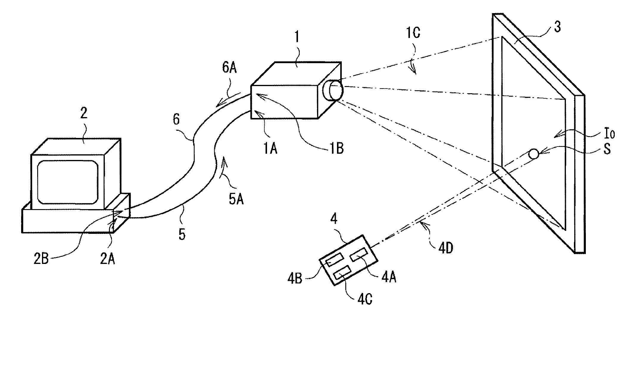
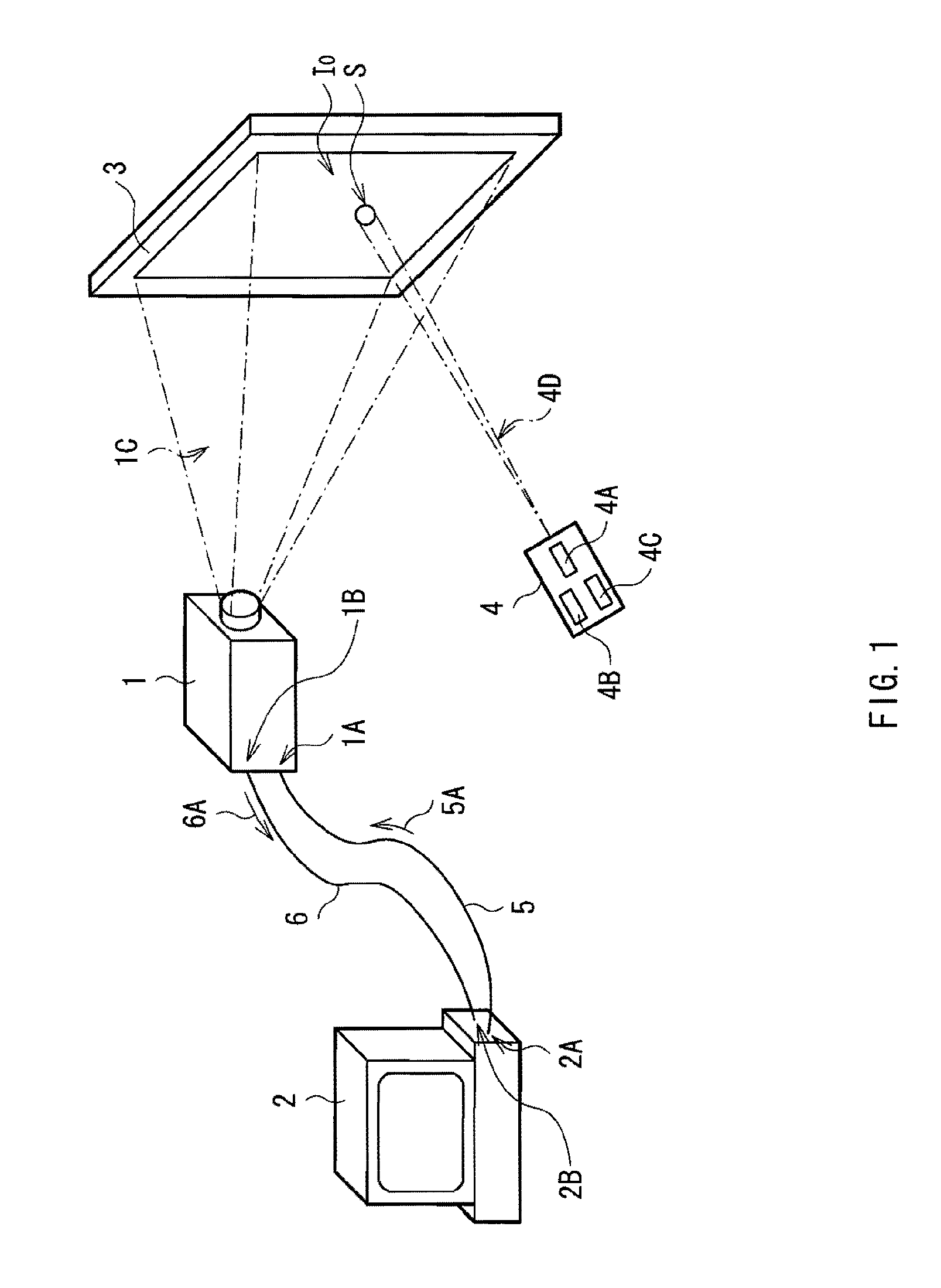
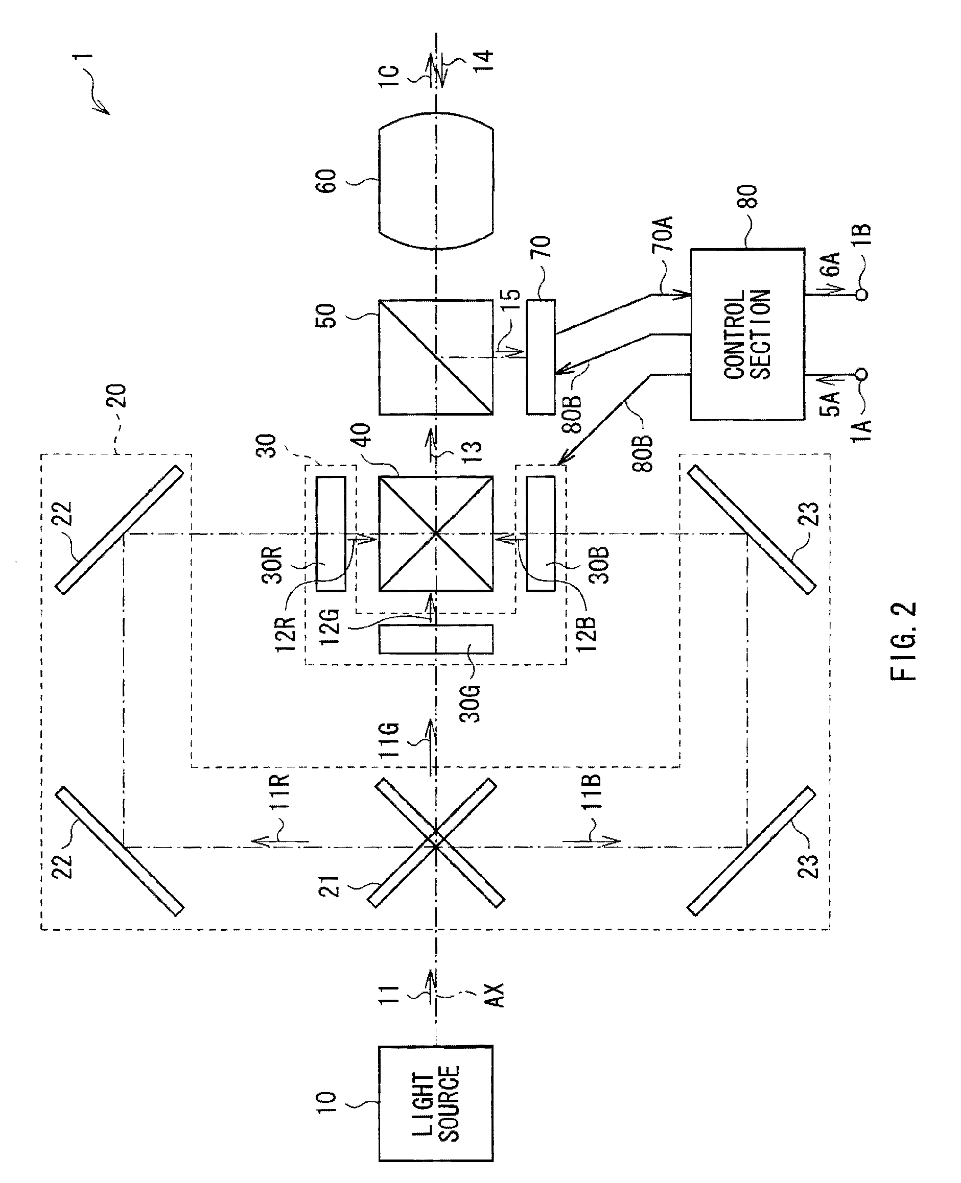
[0026]FIG. 1 illustrates an example of a schematic configuration of an image display system having a projector 1 (image display device) according to a first embodiment of the present invention. FIG. 2 illustrates an example of an internal configuration of the projector 1. The image display system projects, for example, an image displayed on a screen of an information processing unit 2 onto a screen 3 by using the projector 1, and allows the screen 3 to be used substantially as a touch screen by operating a laser pointer 4 like a mouse or a computer mouse (not illustrated) of the information processing unit 2.

[0027]The projector 1 projects the image displayed on the screen of the information processing unit 2 onto the screen 3. The projector 1 is provided with two terminals (an input terminal 1A and an output terminal 1B). To the input terminal 1A, a video signal line 5 is connected. A video signal 5A output from the information processing unit 2 is input to the input terminal 1A via...

second embodiment

[0057]A second embodiment of the present invention will be described.

[0058]FIG. 5 illustrates an example of a schematic configuration of an image display system having a projector 7 (image display device) according to a second embodiment of the present invention. FIG. 6 illustrates an example of an internal configuration of the projector 7 in FIG. 5. The image display system projects, for example, an image displayed on a screen of the information processing unit 2 onto the screen 3 by using the projector 7, and allows the screen 3 to be used substantially as a touch screen by operating a laser pointer 8 like a mouse (not illustrated) of the information processing unit 2.

[0059]The projector 7 of the second embodiment is different from the configuration of the projector 1 of the foregoing embodiment, in that the projector 7 has a receiving section 90. Also, the laser pointer 8 of the second embodiment is different from the configuration of the laser pointer 4 of the foregoing embodime...


PUM


Abstract

The present invention provides an image display device allowing accurate detection of a pointed position on a projection image to be achieved. The image display device include: an image light generating section generating image light based on an input video signal; a projecting section projecting the image light onto a screen to form a projection image; a reflection light splitting section splitting part of reflection light of the projection image from the screen to another direction; a light receiving section receiving the split light; an image generating / obtaining section generating a display image from the video signal and obtaining the projection image corresponding to the inputted video signal from the light receiving section; a position detecting section detecting a position pointed out on the projection image as a pointed position based on the display image and the projection image to output information of the pointed position on the projection image.

Description

BACKGROUND OF THE INVENTION[0001]1. Field of the Invention[0002]The present invention relates to an image display device and a position detecting method, for detecting a position on an image pointed out with a laser pointer, a pointing stick, a finger or the like.[0003]2. Description of the Related Art[0004]At present, there are various methods for operating a computer. Other than a keyboard and a mouse, for example, there are direct-input-type displays in various modes for operating a computer by touching a screen with a finger, a dedicated pen, or the like. The displays of the direct-input type are called touch panels or touch screens (hereinbelow, generically called touch screens). The touch screen is an output interface and also plays a role as a main input interface such as a keyboard and a mouse.[0005]There is a case that the touch screen is provided with a connection terminal such as RS-232, PS / 2, USB, or the like. In the case where the touch screen is provided with such a co...

Claims


Application Information

Patent Timeline
Patent Type & Authority Applications(United States)
IPC IPC(8): H04N9/31G03B21/00
CPCG03B21/00G06F3/037H04N9/3197H04N9/3105H04N9/3194G06F3/048G03B21/006
Inventor TAN, XIAODI
Owner SONY CORP
Why Eureka
Try Eureka