Light source apparatus and projector

Inactive Publication Date: 2010-03-25
OLYMPUS CORP
View PDF3 Cites 11 Cited by
  • Summary
  • Abstract
  • Description
  • Claims
  • Application Information

AI Technical Summary

Benefits of technology

[0035]With the configuration described above, because the cooling level of the cooling part is adjusted on the basis of the measured tube-member tilt angle, it is possible to control the amount of heat radiated by the heat-radiating part.
[0036]According to the present invention, heat generated by the plurality of light sources can be absorbed by the heat-absorbing member, and this heat can be transported to the heat-radiating part by the heat-transporting part and radiated by the heat-radiating part. Therefore, it is n

Problems solved by technology

When the temperature of LEDs increases, the light level decreases, and therefore, when using them as light sources for projectors, it is not possible to provide images having the required

Method used


Image

  • Light source apparatus and projector
  • Light source apparatus and projector
  • Light source apparatus and projector

Examples


first embodiment

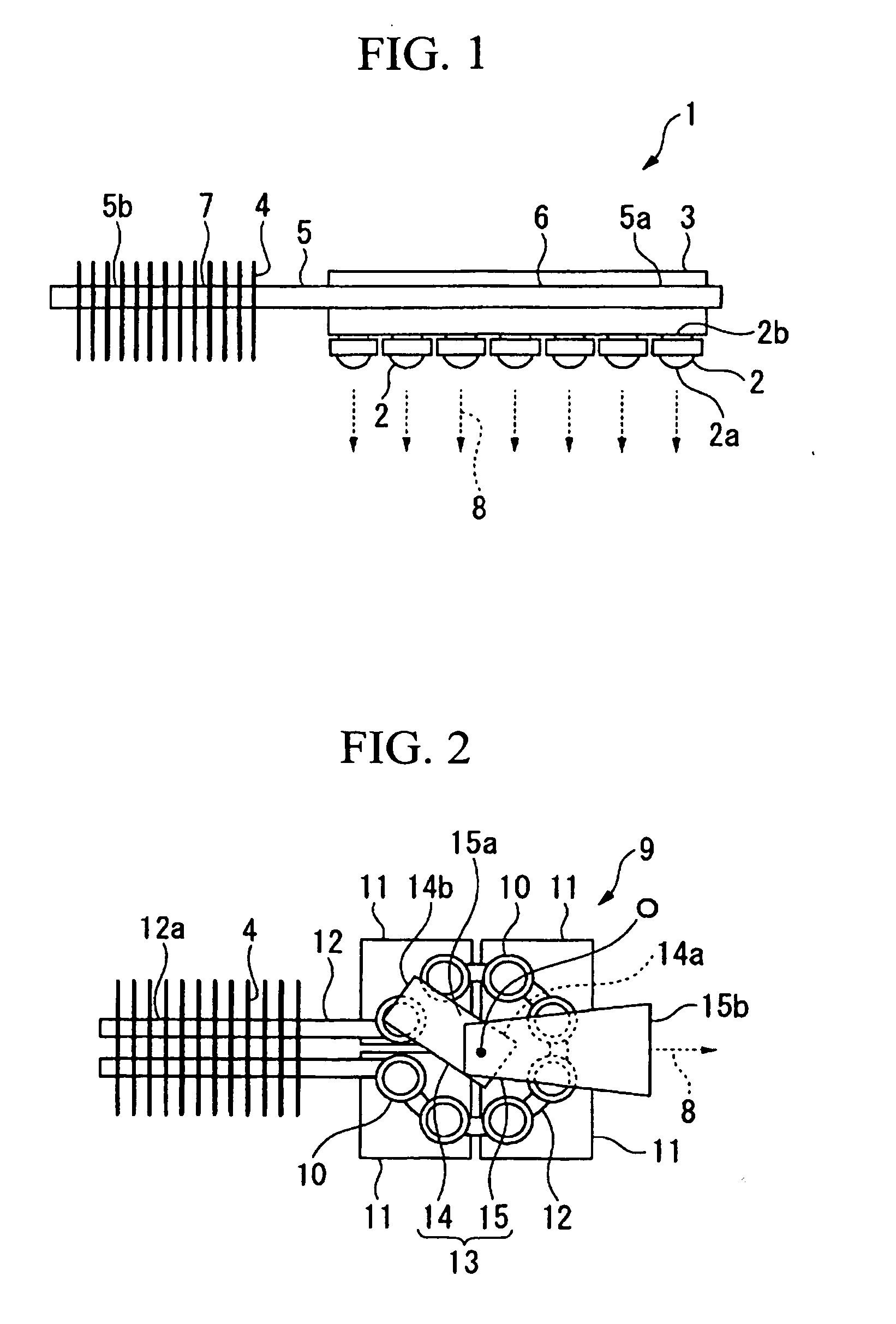
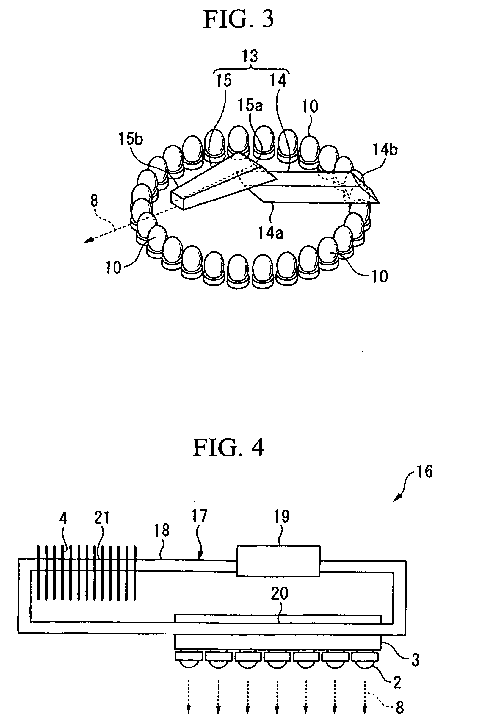
[0055]FIG. 1 is a sectional view of a light source apparatus 1 according to a first embodiment of the present invention. As shown in FIG. 1, the light source apparatus 1 of this embodiment includes a plurality of light sources 2; a single heat-absorbing block 3 which is provided at opposite sides 2b of light-emitting parts 2a of the light sources 2 and which is thermally connected to all of the plurality of light sources 2 to serve as a heat-absorbing member; a heat-radiating part 4 for radiating the heat absorbed by the heat-absorbing block 3; and a heat-transporting part 5 which is thermally connected to the heat-absorbing block 3 at one end 5a and which is thermally connected to the heat-radiating part 4 at another end 5b. The light sources 2 are LEDs. The heat-absorbing block 3 absorbs heat generated by the LEDs, that is, the light sources 2, which emit light, and is formed in the shape of a block made of metal with high thermal conductivity, such as copper. The heat-radiating p...

second embodiment

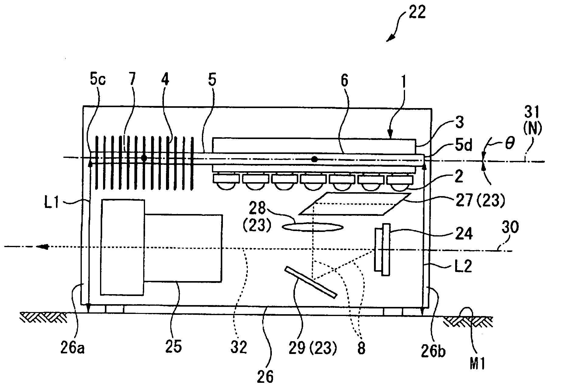
[0064]FIGS. 5 to 8 show a second embodiment of the present invention. In this embodiment, parts that are equivalent to the parts used in the embodiment described above are assigned the same reference numerals, and a description thereof is omitted. FIGS. 5 and 6 are cross-sectional views schematically showing the constituent elements of a projector 22 of this embodiment. FIG. 7 is a sectional view of the projector 22 shown in FIGS. 5 and 6 when used horizontally, and FIG. 8 is a sectional view of the projector shown in FIGS. 5 and 6 when projecting upward.

[0065]The projector 22 according to this embodiment, which is a mounted-type projector used while mounted to a flat mounting surface M1, such as a table or floor, includes a light source apparatus 1; an illumination optical unit 23 which optically operates so that illumination light 8 emitted by the light source apparatus 1 illuminates an illumination area; an image modulation device 24, provided at the illumination area, for modula...

third embodiment

[0073]FIGS. 11 to 17 show a third embodiment according to this invention. In this embodiment, members similar to the members used in the embodiments described above are assigned the same reference numerals, and a description thereof is omitted. FIG. 11 shows a schematic sectional view of a projector of this embodiment. FIG. 12 shows a graph of a computational expression 51 relating a change in tube-member tilt angle Δθ and a light level Y, which is built into a calculation unit 47 in a control unit 43 of a projector 42. FIG. 13 shows a graph of a computational expression 52 relating the change in tube-member tilt angle Δθ and a heat-buildup factor ΔS, which is built into the calculation unit 47 in the control unit 43 of the projector 42. FIG. 14 shows a graph of a computational expression 54 relating the light level Y and an amount of radiated heat Z, which is built into the calculation unit 47 in the control unit 43 of the projector 42. FIGS. 15 to 17 are block diagrams showing a c...


PUM


Abstract

Provided is a light source apparatus for illuminating an illumination area via an illumination optical part, including a plurality of light sources for emitting illumination light; one heat-absorbing member for absorbing heat which the plurality of light sources generates; a heat-radiating part for radiating the heat; and a heat-transporting part thermally connected to the heat-absorbing member and the heat-radiating part; wherein the heat-transporting part is formed of a tube member containing a refrigerant for transmitting the heat and is provided at a position shifted from an irradiation position of the illumination light.

Description

TECHNICAL FIELD[0001]The present invention relates to a light source apparatus having a plurality of light sources and to a projector provided with such a light source apparatus.BACKGROUND ART[0002]In the related art, methods have been proposed for radiating heat generated in light sources used in projectors and so forth. For example, in a projector using an ultra-high-pressure mercury lamp as the light source, a method has been proposed in which a plurality of heat pipes having heat-radiating fins at their ends are provided in a concave reflecting mirror of the ultra-high-pressure mercury lamp (for example, see Japanese Unexamined Patent Application, Publication No. 2000-131764). In addition, in a projector including a light source apparatus formed of a lamp bulb for emitting light and a reflector for reflecting the light that the lamp bulb emits, a method has been proposed in which a heat-conducting member, namely, a metal with high thermal conductivity or a heat pipe, is attached...

Claims


Application Information

Patent Timeline
IPC IPC(8): G03B21/16H05K7/20
CPCF21V29/004F21V29/02F21V29/30F21Y2101/02F21V29/763F21V29/006G03B21/2013F21V29/76G03B21/16F21Y2115/10F28D15/0275F21V29/60F21V29/717
Inventor SUEOKA, YOSHIAKI
Owner OLYMPUS CORP
Why Eureka
Try Eureka