Movable body apparatus, movable body drive method, exposure apparatus, exposure method, and device manufacturing method

a technology of movable body and drive method, which is applied in the direction of photomechanical treatment, printing, instruments, etc., can solve the problems of short-term variation of measurement value due, reducing the measurement accuracy of the encoder system, and the beam path of the laser interferometer cannot be ignored. , to achieve the effect of good precision

Active Publication Date: 2010-03-25
NIKON CORP
View PDF35 Cites 82 Cited by
  • Summary
  • Abstract
  • Description
  • Claims
  • Application Information

AI Technical Summary

Benefits of technology

[0017]According to this method, because the movable body can be driven with good precision, it becomes possible to transfer a pattern on the object by driving the object mounted on the movable body with good precision, and irradiating the energy beam on the object.

Problems solved by technology

However, requirements for a fine movement stage position control with higher precision are increasing due to finer patterns that accompany higher integration of semiconductor devices recently, and as a consequence, short-term variation of measurement values due to the influence of temperature fluctuation and / or temperature gradient of the atmosphere on the beam path of the laser interferometer can no longer be ignored.
However, in the exposure apparatus related to the fifth embodiment of PCT International Publication No, 2008 / 038752, because the encoder main body is provided at the stage surface plate supported by suspension by the projection optical system surface plate via the suspension support member, it could be affected by vibration and the like due to the drive of the stage, which could reduce the measurement accuracy of the encoder system.
Further, the placement of the encoder main body adopted in the exposure apparatus related to the fifth embodiment of PCT International Publication No. 2008 / 038752 was difficult to adopt in the case of measuring positional information of the fine movement stage using a stage device that is a combination of a coarse movement stage that moves on a surface plate and a fine movement stage that holds a wafer and relatively moves on the coarse movement stage with respect to the coarse movement stage, or a stage device of a so-called coarse / fine movement structure, because the coarse movement stage came between the fine movement stage and the surface plate.

Method used


Image

  • Movable body apparatus, movable body drive method, exposure apparatus, exposure method, and device manufacturing method
  • Movable body apparatus, movable body drive method, exposure apparatus, exposure method, and device manufacturing method
  • Movable body apparatus, movable body drive method, exposure apparatus, exposure method, and device manufacturing method

Examples


Embodiment Construction

[0037]An embodiment of the present invention will be described below, with reference to FIGS. 1 to 11B.

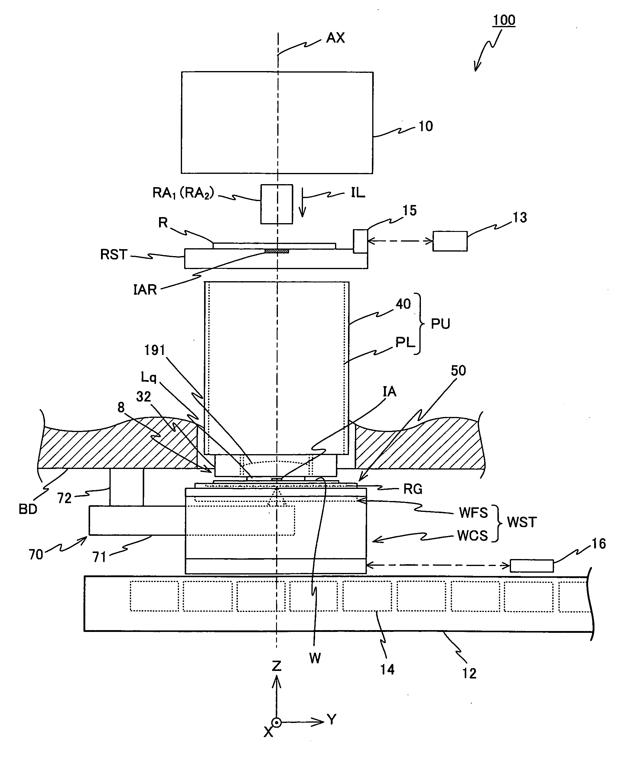
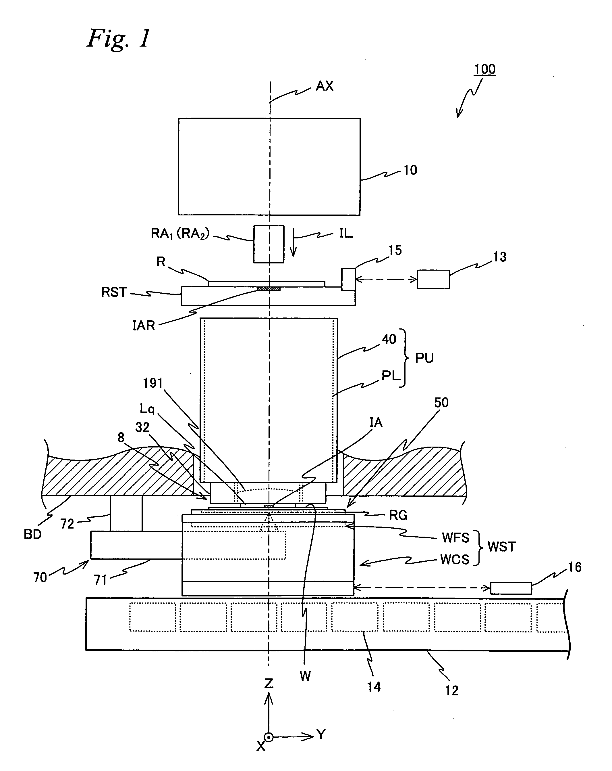
[0038]FIG. 1 shows a schematic configuration of an exposure apparatus 100 in the embodiment. Exposure apparatus 100 is a projection exposure apparatus by the step-and-scan method, or a so-called scanner. As it will be described later, a projection optical system PL is arranged in the embodiment, and in the description below, a direction parallel to an optical axis AX of projection optical system PL will be described as the Z-axis direction, a direction within a plane orthogonal to the Z-axis direction in which a reticle and a wafer are relatively scanned will be described as the Y-axis direction, a direction orthogonal to the Z-axis and the Y-axis will be described as the X-axis direction, and rotational (inclination) directions around the X-axis, the Y-axis, and the Z-axis will be described as θx, θy, and θz directions, respectively.

[0039]As shown in FIG. 1, exposure apparatus 100...


PUM


Abstract

A drive system drives a movable body, based on measurement results of a first measurement system which measures the position of the movable body in an XY plane by irradiating a measurement beam from an arm member on a grating placed on a surface parallel to the XY plane of the movable body. In this case, because a configuration in which the arm member irradiates a measurement beam on the grating is employed, there is no adverse effect due to the drive of the moving body, unlike the case when an encoder system is arranged on a stage surface plate. Accordingly, it becomes possible to drive the movable body with good precision.

Description

CROSS-REFERENCE TO RELATED APPLICATIONS[0001]This non-provisional application claims the benefit of Provisional Application No. 61 / 098,893 filed Sep. 22, 2008, Provisional Application No. 61 / 098,902 filed Sep. 22, 2008, and Provisional Application No. 61 / 213,351 filed Jun. 1, 2009, the disclosures of which are hereby incorporated herein by reference in its entirety.BACKGROUND OF THE INVENTION[0002]1. Field of the Invention[0003]The present invention relates to movable body apparatuses, movable body drive methods, exposure apparatuses, exposure methods, and device manufacturing methods, and more particularly, to a movable body apparatus including a moving body which is movable along a predetermined plane and a movable body drive method to drive the movable body, an exposure apparatus which is equipped with the movable body apparatus and an exposure method which uses the movable body drive method, and a device manufacturing method which uses the exposure apparatus or the exposure meth...

Claims


Application Information

Patent Timeline
Patent Type & Authority Applications(United States)
IPC IPC(8): G03B27/42G03B27/58
CPCG03F7/707G03F7/70775G03F7/70716
Inventor SHIBAZAKI, YUICHI
Owner NIKON CORP
Why Eureka
Try Eureka