Structure of MEMS electroacoustic transducer and fabricating method thereof

a technology of electroacoustic transducers and electroacoustic transducers, which is applied in the direction of electromechanical transducers, semiconductor electrostatic transducers, diaphragms of transducers, etc., can solve the problems of difficult control of the quality of the polymer layer, unsatisfactory etc., to improve the sensitivity of the electroacoustic transducer, easy integration, and process

Active Publication Date: 2010-03-25
UNITED MICROELECTRONICS CORP
View PDF10 Cites 29 Cited by
  • Summary
  • Abstract
  • Description
  • Claims
  • Application Information

AI Technical Summary

Benefits of technology

[0030]In view of the above, the structure of MEMS electroacoustic transducer of the present invention adopts a silicon material layer as the sealing layer, thus effectively improving the sensitivity of the MEMS electroacoustic transducer.
[0031]Furthermore, the fabricating method of a structure of MEMS electroacoustic transducer of the present invention can effectively control the film quality of the sealing layer, thereby fabricating the seal...

Problems solved by technology

However, the material of the polymer layer is overly soft, which causes the problem that the sensitivity of the electroacoustic transducer is unsatisfactory.
Furthermor...

Method used


Image

  • Structure of MEMS electroacoustic transducer and fabricating method thereof
  • Structure of MEMS electroacoustic transducer and fabricating method thereof
  • Structure of MEMS electroacoustic transducer and fabricating method thereof

Examples


first embodiment

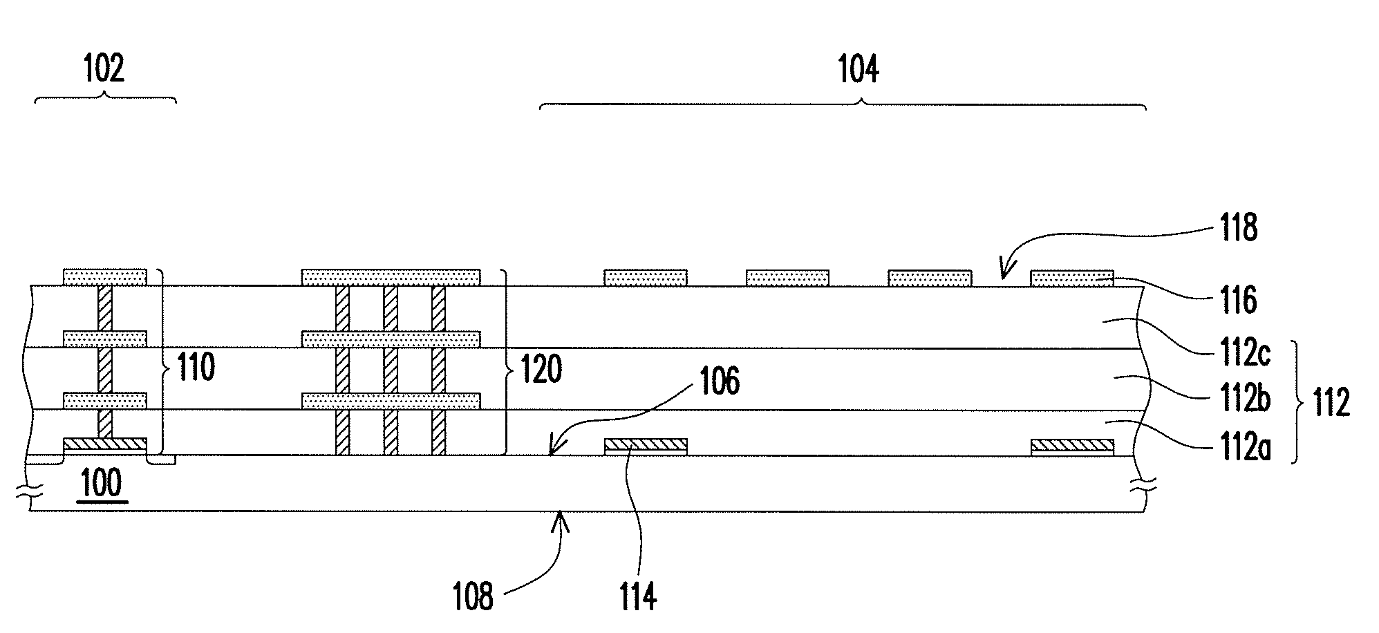
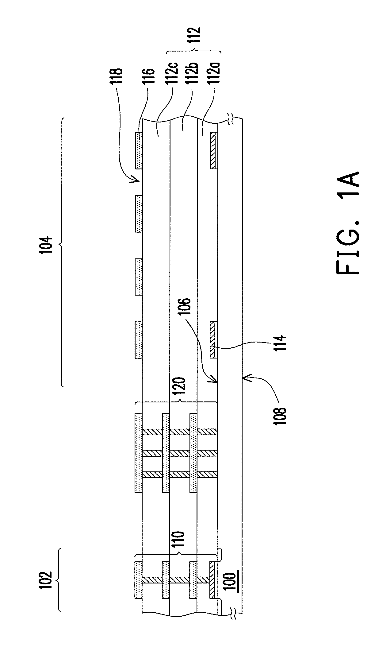
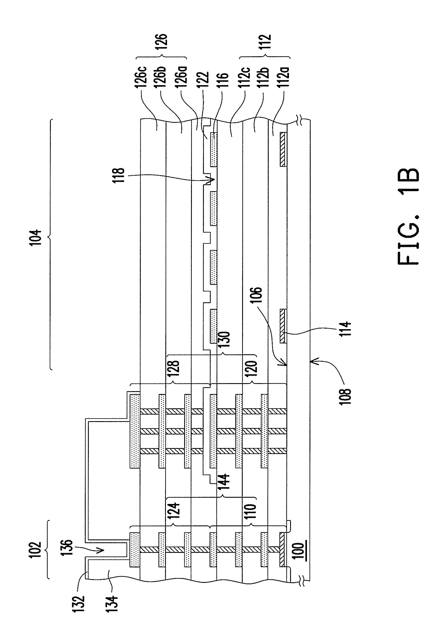
[0037]FIGS. 1A to 1D are cross-sectional views illustrating processes of fabricating a structure of micro-electro-mechanical systems (MEMS) electroacoustic transducer according to the present invention.

[0038]First, referring to FIG. 1A, a substrate 100 is provided. The substrate 100 includes a circuit region 102 and an MEMS device region 104. The substrate 100 has a front side 106 and a back side 108. The substrate 100 is, for example, a silicon substrate. Wherein, one of the ordinary skill in the art could modulate the disposition relationship between the circuit region 102 and the MEMS device region 104 depended on demand. For example, the MEMS device region 104 is located at the right side of the circuit region 102 in the first embodiment. In other embodiment, the MEMS device region 104 may be located at the left side of the circuit region 102.

[0039]Then, a metal interconnect structure 110 is formed on the front side 106 of the substrate 100 in the circuit region 102. The fabrica...

second embodiment

[0057]FIGS. 2A to 2C are cross-sectional views illustrating processes of fabricating a structure of MEMS electroacoustic transducer according to the present invention.

[0058]First, referring to FIG. 2A, a substrate 200 is provided. The substrate 200 includes a circuit region 202, an MEMS device region 204, and a vent hole region 206. The substrate 200 is, for example, a silicon substrate. Wherein, one of the ordinary skill in the art could modulate the disposition relationship among the circuit region 202, the MEMS device region 204 and the vent hole region 206 depended on demand. For example, the circuit region 202 is located at one side of the MEMS device region 204, and the vent hole region 206 is located at the other side of the MEMS device region 204 in the second embodiment. In other embodiment, the circuit region 202 may be located at one side of the vent hole region 206, and the MEMS device region 204 may be located at the other side of the vent hole region 206.

[0059]Then, a ...


PUM

PropertyMeasurementUnit
Structureaaaaaaaaaa
Shapeaaaaaaaaaa
Electrical conductoraaaaaaaaaa

Abstract

A structure of a micro-electro-mechanical systems (MEMS) electroacoustic transducer includes a substrate, a diaphragm, a silicon material layer, and a conductive pattern. The substrate includes an MEMS device region. The diaphragm has openings, and is disposed in the MEMS device region. A first cavity is formed between the diaphragm and the substrate. The silicon material layer is disposed on the diaphragm and seals the diaphragm. The conductive pattern is disposed beneath the diaphragm in the MEMS device region.

Description

BACKGROUND OF THE INVENTION[0001]1. Field of the Invention[0002]The present invention generally relate to a micro-electro-mechanical systems (MEMS) structure and a fabricating method thereof, in particular, to a structure of MEMS electroacoustic transducer and a fabricating method thereof.[0003]2. Description of Related Art[0004]Electroacoustic transducers are capable of converting acoustic waves into electrical signals or converting electrical signals into acoustic waves by the use of diaphragms, so as to serve as the microphones or speakers. The electroacoustic transducers have wide applications, such as in mobile phone, digital camera, hands free phone, and notebook computer products in the computer communication industry, or in the medical instruments such as hearing aids and cochlear implant products.[0005]Along with the rapid development of the electronic industry and progress of the semiconductor process and packaging technique, the electroacoustic transducer products are des...

Claims


Application Information

Patent Timeline
IPC IPC(8): H04R3/00H04R31/00
CPCB81B2201/0271H04R3/00H04R19/005Y10T29/49002B81B3/0021H04R7/00H04R2499/11H04R31/00B81C2201/014
Inventor LAN, BANG-CHIANGWANG, MING-IHO, LI-HSUNWU, HUI-MINCHEN, MINHUANG, CHIEN-HSIN
Owner UNITED MICROELECTRONICS CORP
Why Eureka
Try Eureka