Medical image diagnostic device

a diagnostic device and medical image technology, applied in the field of tracking technology, can solve the problems of large tracking operation error, difficult to accurately track the tracking point, and accumulation of errors, so as to maintain the accuracy of tracking over a multiplicity of motion cycles, and reduce the accumulation of tracking errors

Inactive Publication Date: 2010-03-25
HITACHI LTD
View PDF3 Cites 52 Cited by
  • Summary
  • Abstract
  • Description
  • Claims
  • Application Information

AI Technical Summary

Benefits of technology

[0015]The medical diagnostic imaging apparatus according to the invention can lessen accumulation of tracking errors by performing template matching using a key template in one or ...

Problems solved by technology

Therefore, a tracking point is tracked by a conventional template matching technique, tracking operation error becomes very large.
In addition, tracking results of a tracking point by a template matching technique (position coordinates of the tracking point) contains errors originating from sampling, quantization,...

Method used


Image

  • Medical image diagnostic device
  • Medical image diagnostic device
  • Medical image diagnostic device

Examples


first embodiment

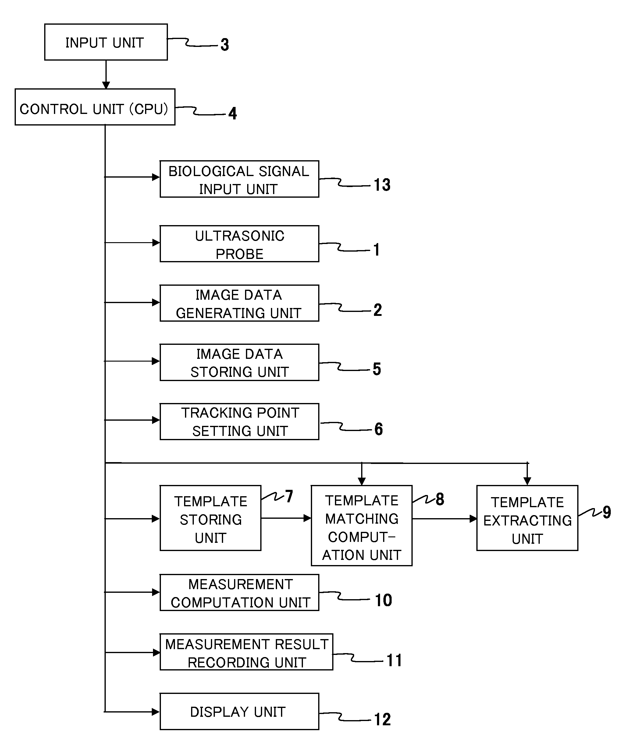
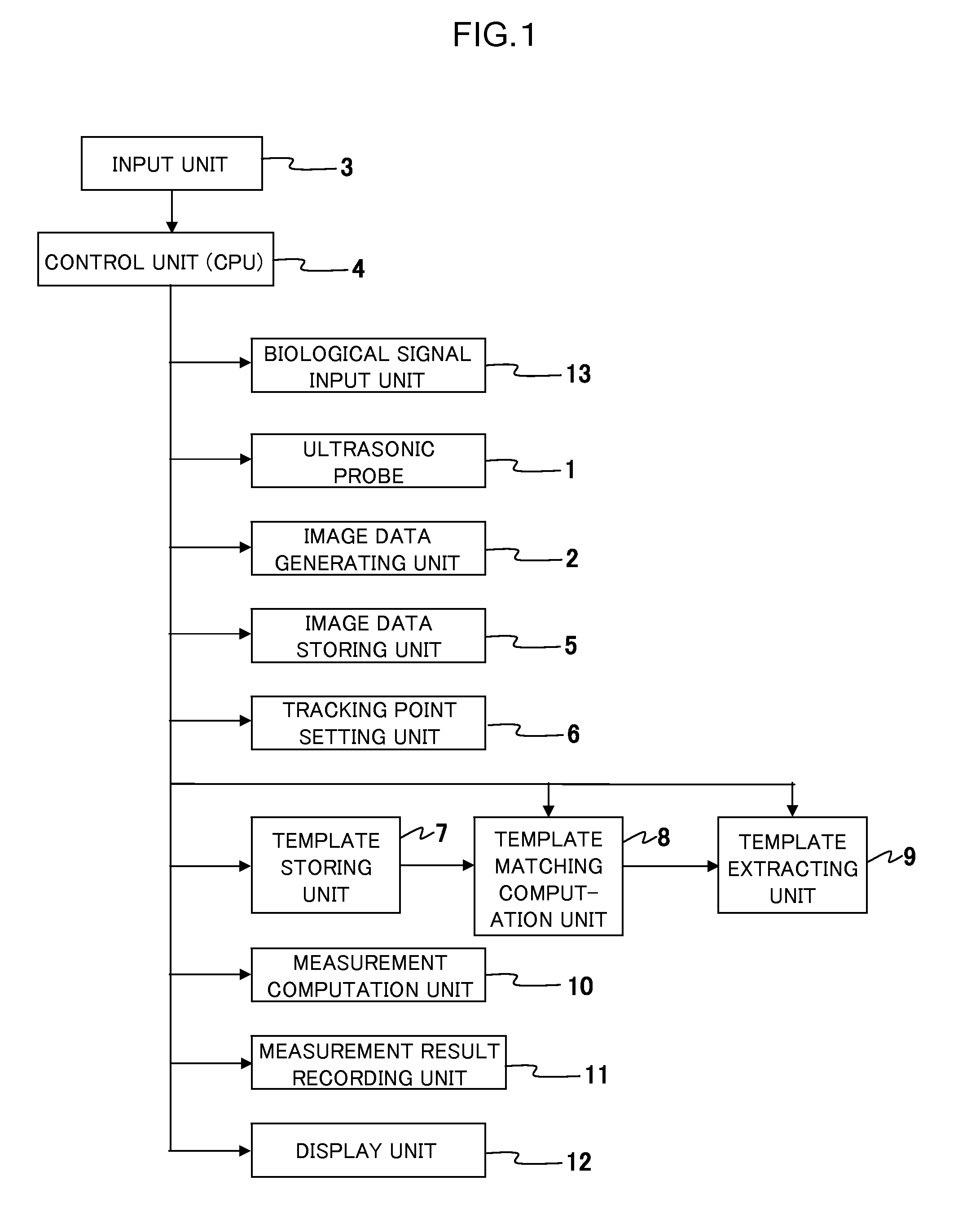
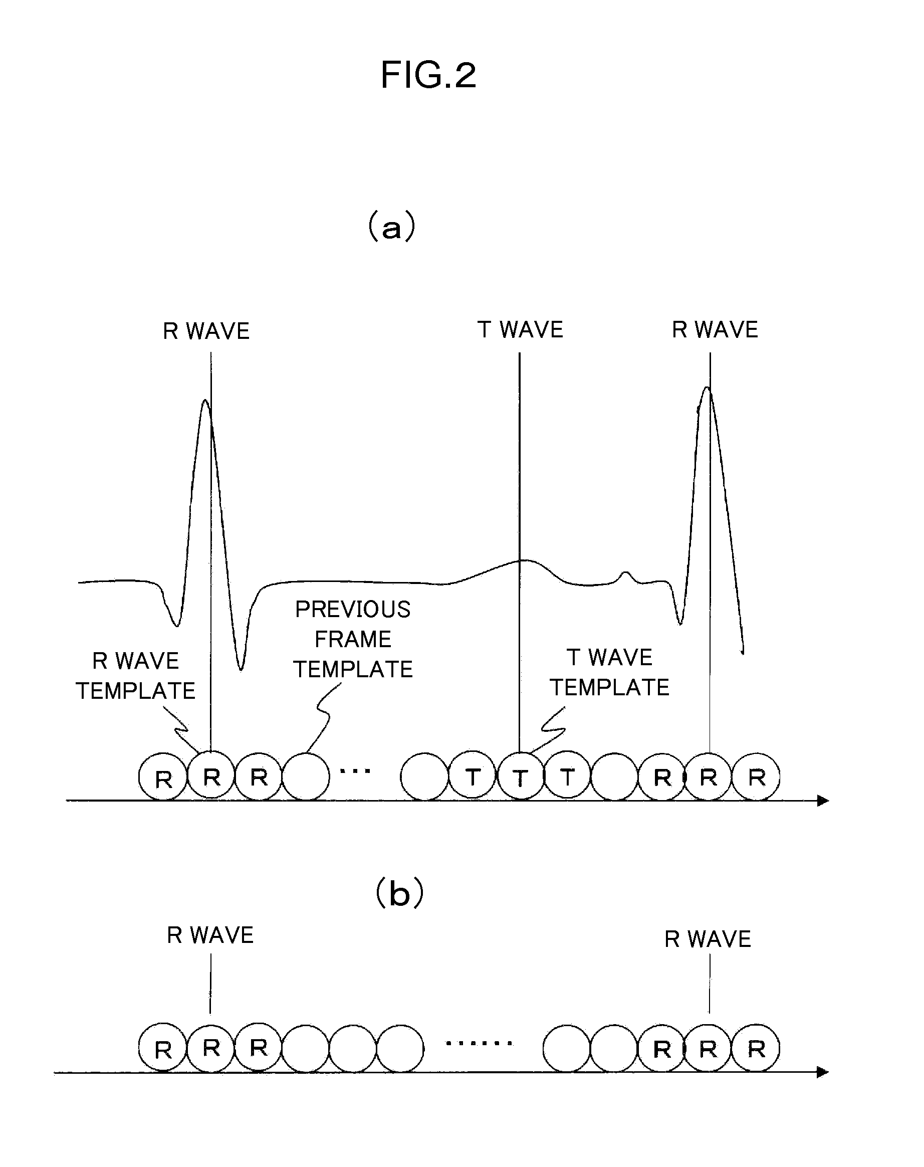
[0042]Next, a first embodiment of the ultrasonic diagnostic apparatus of the invention will be described below. This embodiment is such that the tracking operation is performed while switching one or more key templates of cardiac phases according to the cardiac phases. With reference to FIGS. 2 and 3, this embodiment will be described specifically taking the tracking operation process for the tracking points set at one or a plurality of points on the image of the heart, a region of interest, of the test object that is displayed on the display screen of the display unit 12. This embodiment shows an example in which error correction for tracking points is performed at an R wave time phase and a T wave time phase during one cardiac cycle.

[0043]Before starting the tracking process, the examiner at first performs, as the preparation, an acquiring operation (S1) for key templates at a R wave cardiac time phase and a T wave cardiac time phase of the cardiac cycle. The acquiring operation f...

second embodiment

[0053]Next, a second embodiment of the invention will be described. The first embodiment above is such that a tracking operation is performed while switching one or more key templates of cardiac phases according to the cardiac phases. The second embodiment is such that the template matching is performed for an arbitrary frame (image) of a cardiac phase while using a plurality of key templates. Hereinbelow, this embodiment will be described with reference to FIGS. 4 and 5. The template matching starts with the step of acquiring key templates for the R wave cardiac phase and the T wave cardiac phase, correlating the key templates with the respective time phases, and storing them in the template storing unit 7 (S101), as in the process flow shown in FIG. 3. When the acquisition of the key templates ends, the control unit 4 starts a tracking process (S102). If the next frame for which an ultrasonic image of the heart is read out from the image data storing unit 5 exists (S103), the proc...


PUM


Abstract

A medical diagnostic imaging apparatus is provided that is capable of accurately tracking motions of a moving organ that moves periodically over a plurality of periods.
The medical diagnostic imaging apparatus includes a matching computation unit for performing a matching computation between a template extracted containing a tracking point on one image and another image, and a template extracting unit for extracting, from the other image, a region correlated with the template as a template of the other image by the matching computation, whereby a movement of the tracking point is tracked based on the extracted template. The template extracting unit extracts, as a key template, a region containing one or more tracking points set on an image at least one time phase within a motion cycle of the moving organ. The matching computation unit performs the matching computation using the key template in the vicinity of the time phase at which the key template is extracted.

Description

TECHNICAL FIELD[0001]The present invention relates to a tracking technology for tracking movement of a moving organ in an image on a medical diagnostic imaging apparatus.BACKGROUND ART[0002]It is useful for diagnosis of cardiac lesion to quantitatively evaluate cardiac output of blood, heart chamber volume, and thickness of cardiac muscle. For this reason, evaluation of these cardiac functions is carried out by medical diagnostic imaging apparatus, such as ultrasonic diagnostic imaging apparatus, magnetic resonance diagnostic imaging apparatus, and X-ray CT diagnostic imaging apparatus.[0003]For example, in diagnosis of cardiac functions using an ultrasonic diagnostic apparatus, movements of valves and cardiac muscle walls, wall thickness, changes of heart chamber volume are measured by setting a tracking point set on a wall of a cardiac muscle and finding out to what location the tracking point has moved in association with pulsation of the heart. This determination of displacement...

Claims


Application Information

Patent Timeline
IPC IPC(8): G06K9/00G16H30/20G16H30/40
CPCA61B5/055A61B6/032A61B6/503A61B8/065A61B8/08G06T2207/30048G06F19/321G06K9/3216G06K2209/051G06T7/2033G06T2207/10132A61B8/0858G06T7/246G16H30/20G16H30/40G06V10/245G06V2201/031
Inventor CHOUNO, TOMOAKI
Owner HITACHI LTD
Why Eureka
Try Eureka