Radio Base Station and Receiver Fault Diagnosis Method

a technology of fault diagnosis and radio base station, which is applied in the direction of transmission monitoring, line-fault/interference reduction, amplitude demodulation, etc., can solve problems such as amplifier or other device damage, fault detection, and deterioration of intermodulation distortion characteristics

Inactive Publication Date: 2010-03-25
HITACHI LTD
View PDF10 Cites 28 Cited by
  • Summary
  • Abstract
  • Description
  • Claims
  • Application Information

AI Technical Summary

Benefits of technology

[0031]According to the present invention, it is possible to detect a fault in which the intermodulation distortion characteristics of a receiver deteriorate. According to the present invention, it is possible to detect a fault in which the intermodulation distortion char

Problems solved by technology

With the techniques described above, if an amplifier or other device that constitutes a receiver in a base station becomes defective and a gain error is detected, for example, a fault can be detected.
Faults in the amplifier or other device include a fault in which only the intermodulation distortion characteristics deteriorate.
In such a case, the fault cannot be detected with the above-described techniques.
In a system that performs upstream electric power control, for example, deterioration in the intermodulation distortion characteristics c

Method used


Image

  • Radio Base Station and Receiver Fault Diagnosis Method
  • Radio Base Station and Receiver Fault Diagnosis Method
  • Radio Base Station and Receiver Fault Diagnosis Method

Examples


Embodiment Construction

[0038]An embodiment of the present invention will be described below with reference to the drawings.

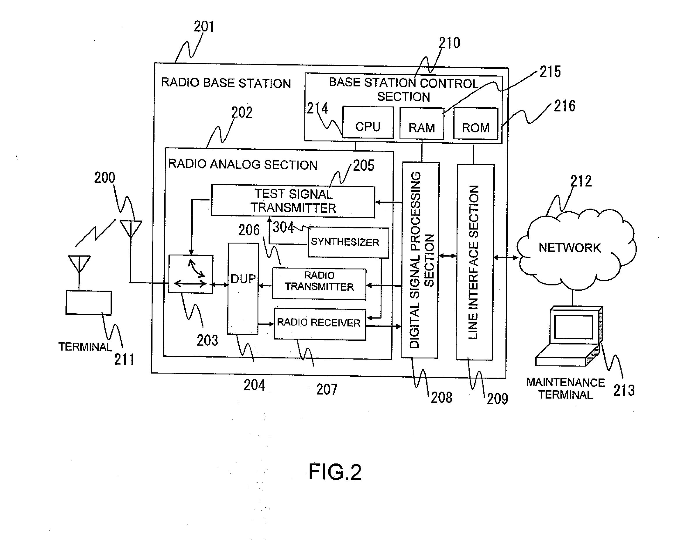
[0039]FIG. 2 shows the structure of a radio base station 201 according to an embodiment of the present invention.

[0040]The radio base station 201 includes, for example, a radio analog section 202, a digital signal processing section 208, a line interface section 209, and a base station control section 210.

[0041]The radio analog section 202 is connected to an antenna 202 used for both transmission and receiving. The radio analog section 202 includes, for example, a duplexer (DUP) 204 for separating a downstream radio signal and a upstream radio signal, a radio transmitter 206, a radio receiver 207, a test signal transmitter 205 used for fault diagnosis, a synthesizer 304, and a coupler 203 for inputting a test signal to the radio receiver 207.

[0042]The digital signal processing section 208 performs data modulation and demodulation, and digital processing for a radio signal and a test s...


PUM


Abstract

Even if a receiver has a normal gain and a lowered intermodulation distortion characteristics, a fault detection is possible. A test signal transmitter sends a test signal having at least two frequencies to a radio receiver through a coupler. A digital signal processing section receives a signal which includes an IM3 component generated by the radio receiver and measures the electric power of fundamental wave components and the IM3 component. Then, the digital signal processing section calculates the gain of the radio receiver and IIP3, which is an index for intermodulation distortion characteristics, of the radio receiver 207 from the calculated electric power. A base station control section determines whether the gain and IIP3 of the radio receiver fall in predetermined ranges to determine whether the radio receiver works normally or has a fault.

Description

CLAIM OF PRIORITY[0001]The present application claims priority from Japanese patent application JP 2008-242051 filed on Sep. 22, 2008, the content of which is hereby incorporated by reference into this application.BACKGROUND OF THE INVENTION[0002]1. Field of the Invention[0003]The present invention relates to radio base stations and receiver fault diagnosis methods, and more particularly, to a radio base station having a transmitter for a diagnostic test and a receiver fault diagnosis method for the radio base station.[0004]2. Description of the Related Art[0005]Recent mobile communication systems are used not only for voice calls but also widely for data communication. As the number of data communication users has been increased, it is demanded that the data communication rate be increased. To handle the increased number of users and the demand for a higher data communication rate, a recent base station has started using multiple carriers. The number of carriers the base station tr...

Claims


Application Information

Patent Timeline
IPC IPC(8): H04B17/00H04B7/005
CPCH04B17/0085H04B17/327H04W24/06
Inventor NAKANO, HARUOHORI, KAZUYUKITAIRA, MASANORICHIBA, TAKAHIROMAGARA, YASUYUKI
Owner HITACHI LTD
Why Eureka
Try Eureka