Method for Controlling a Micro-Hybrid Electric Vehicle with an Automatic Transmission

a technology of hybrid electric vehicles and automatic transmissions, applied in vehicle position/course/altitude control, process and machine control, instruments, etc., can solve the problems of not providing electric vehicle launch torque nor full regenerative power, and achieve the effect of minimal regenerative energy recovery, reduced size, cost and weight of hybrid electric vehicle powertrains

Inactive Publication Date: 2010-03-25
FORD GLOBAL TECH LLC
View PDF19 Cites 56 Cited by
  • Summary
  • Abstract
  • Description
  • Claims
  • Application Information

AI Technical Summary

Benefits of technology

[0008]Because of the power limitations of a micro-HEV using the control method of the invention, the starter-generator results in a fuel economy benefit associated primarily with an engine stop and start function, which turns off the engine during engine idle when the vehicle is at rest. At that time the engine is not required to provide motive power. This function may be of more significance than a regenerative braking function for energy recovery.
[0009]If the power requirement of the hybrid electric vehicle is approximately 10 kw, for example, a fuel economy benefit (e.g., an EPA metro-highway fuel economy benefit) for the micro-hybrid powertrain of the invention due to the engine stop and start function may be as high as approximately 5%. Any braking energy recovery benefit, on the other hand, would be in addition to this fuel economy benefit, and would vary between 1% and 5%. If the regenerative braking capability of the micro-HEV would increase, the cost-benefit ratio would decrease relative to that of a conventional hybrid electric vehicle powertrain.
[0010]The micro-HEV control method of the present invention will shut off the engine and disconnect the engine for all braking events rather than using the starter-generator to collect braking energy. The engine will be disconnected from the traction wheels using the neutral gear of a power-shift, multiple-ratio automatic transmission, which is part of the vehicle powertrain. Using the design approach of the present invention, the starter-generator need only be sized for rapid and warm engine starts, rather than braking energy recovery. Due to the absence of a full regenerative mode during braking, the battery can be made smaller and less expensive than a battery for hybrid electric vehicle powertrains with more regenerative energy recovery ability.

Problems solved by technology

For example, it does not provide electric vehicle launch torque nor full regenerative power.

Method used


Image

  • Method for Controlling a Micro-Hybrid Electric Vehicle with an Automatic Transmission
  • Method for Controlling a Micro-Hybrid Electric Vehicle with an Automatic Transmission
  • Method for Controlling a Micro-Hybrid Electric Vehicle with an Automatic Transmission

Examples


Embodiment Construction

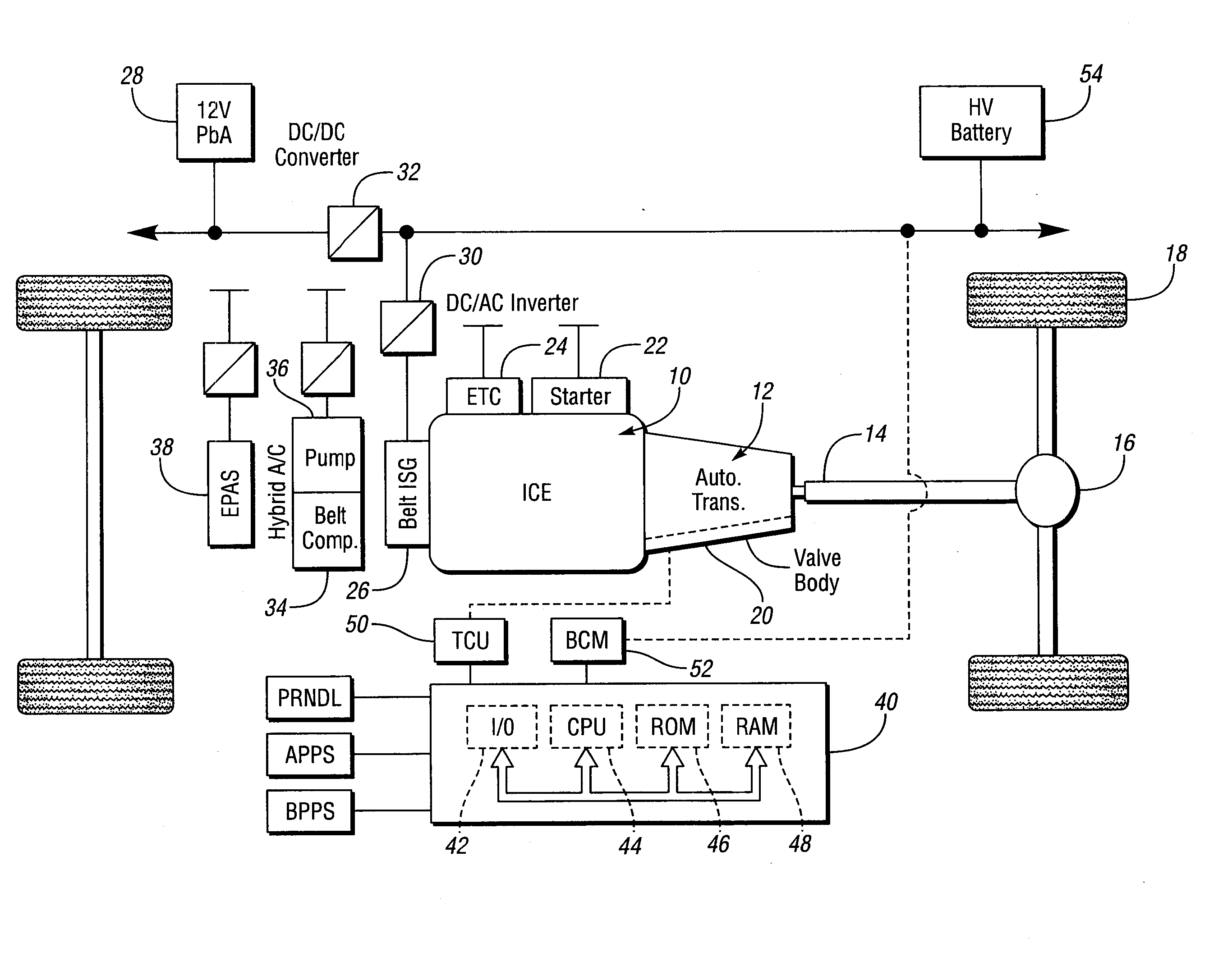
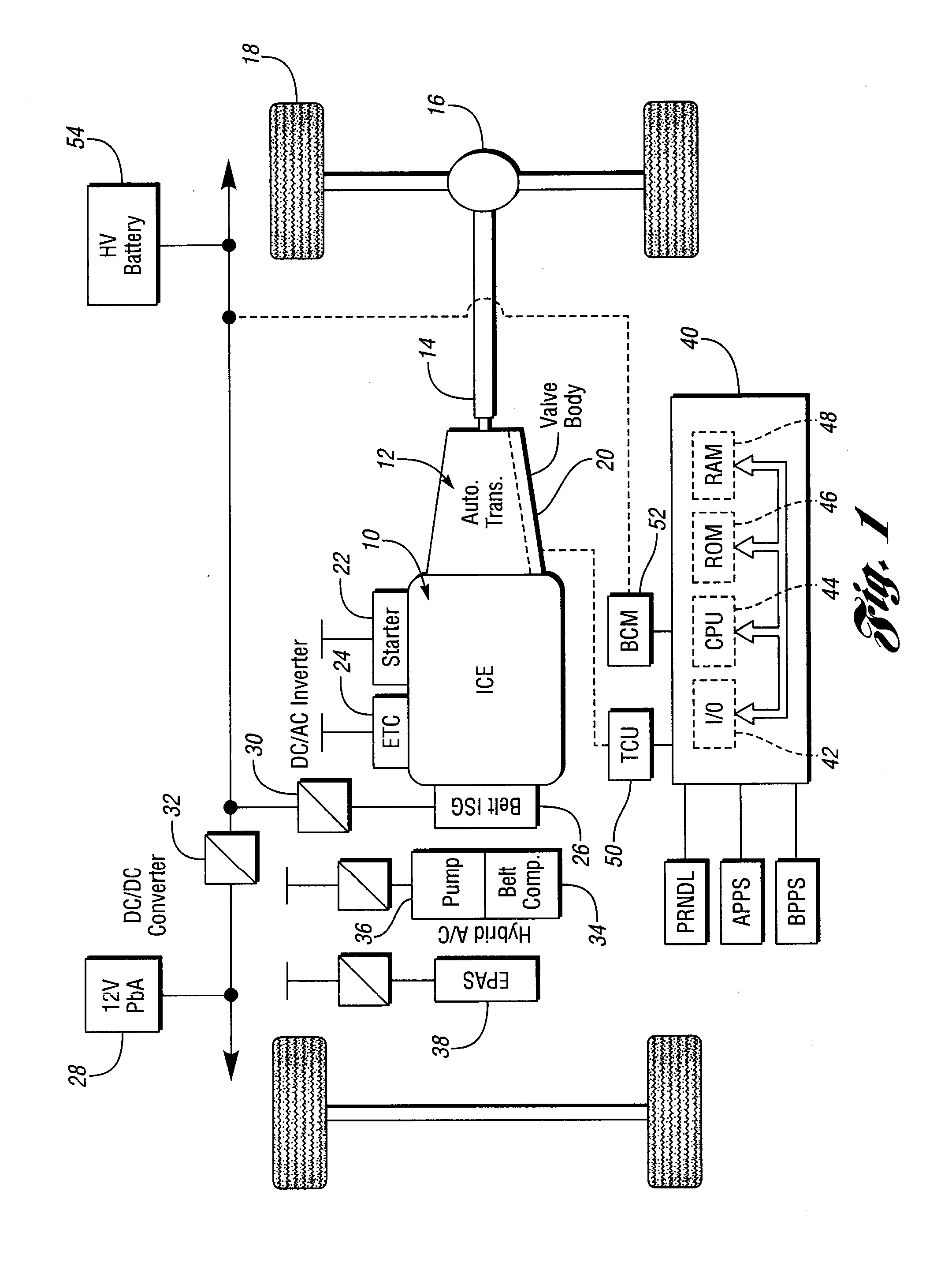
[0017]FIG. 1 schematically illustrates an internal combustion engine 10 and a multiple-ratio automatic transmission 12. Torque delivered from a crankshaft of the internal combustion engine 10 is delivered through multiple-ratio gearing of the transmission 12 to driveshaft 14 and to final drive differential-and-axle assembly 16 for traction wheels 18. The gearing for the transmission 12 establishes multiple torque ratios under the control of a valve body 20. The ratios are established by engageable and disengageable clutches and brakes in a conventional fashion. The transmission may be configured for a neutral state by disengaging a forward drive clutch in usual fashion.

[0018]A starter motor, schematically shown at 22, under the control of a low voltage battery, not shown, can be used to start engine 10 under cold start conditions. An electronic throttle control for the engine 10 is shown at 24 in block diagram form.

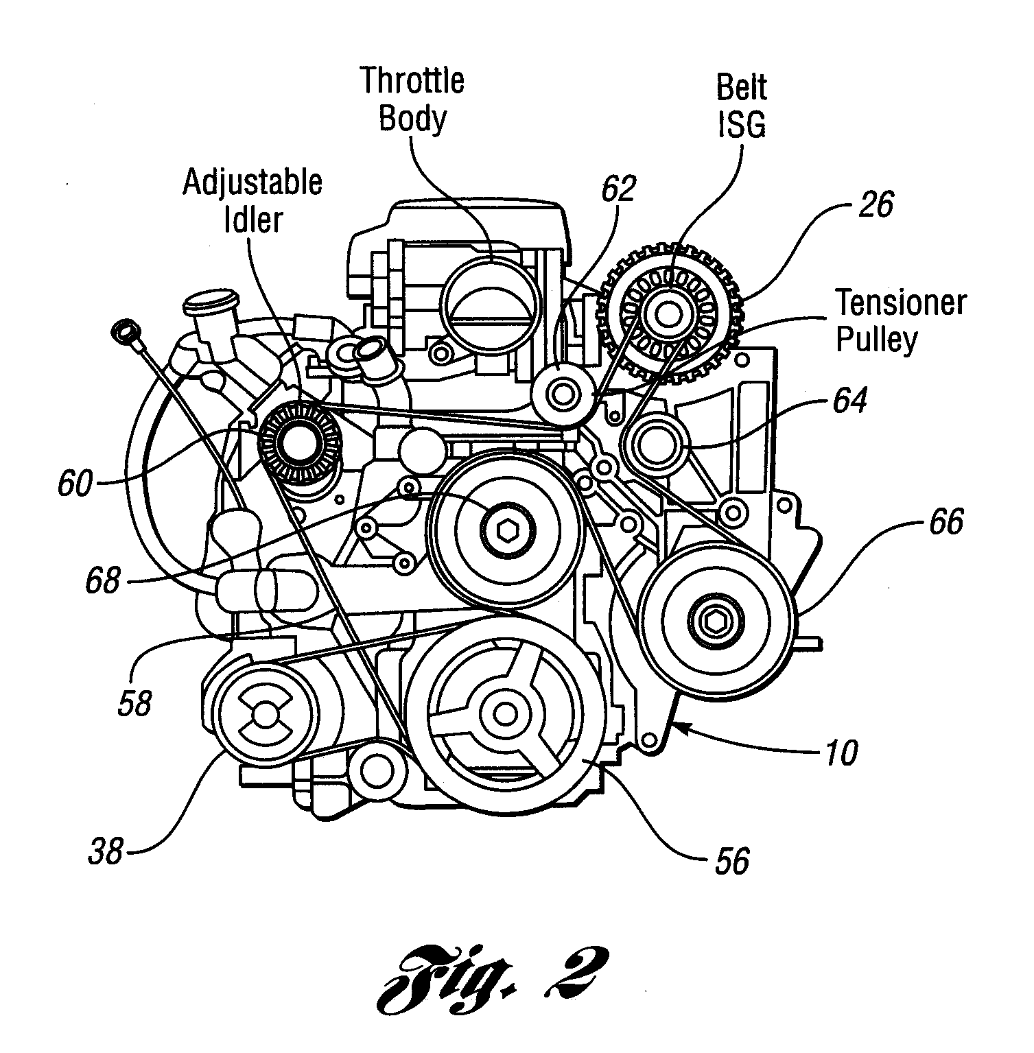
[0019]The engine 10 is drivably connected to a crankshaft pulley, wh...


PUM


Abstract

The micro-hybrid vehicle powertrain of the invention includes a geared transmission, an engine and a starter-generator mechanically coupled to the engine to start the engine as the transmission is shifted into gear. The engine is stopped when a vehicle brake is applied.

Description

BACKGROUND OF THE INVENTION[0001]1. Field of the Invention[0002]The invention relates to an operating strategy for a micro-hybrid electric vehicle using an engine start and stop sequence to obtain optimum fuel economy.[0003]2. Background Art[0004]Known hybrid electric vehicle powertrains typically include separate power flow paths from an electric machine power source and from a mechanical power source, such as an internal combustion engine. Transmission gearing distributes power from the separate power sources to vehicle traction wheels. The electric machine may act as a motor or as a generator. When it acts as a generator in a power regenerative mode, mechanical inertia energy may be distributed to the generator, which converts it to electric energy to charge the battery. The electric machine acts as a generator, for example, to charge a powertrain battery during engine braking.[0005]Since the engine is mechanically coupled to the generator, the generator may act as a motor to sta...

Claims


Application Information

Patent Timeline
Patent Type & Authority Applications(United States)
IPC IPC(8): B60W20/00
CPCB60K6/485B60W10/06B60W10/11Y02T10/6226B60W20/00B60W30/18018B60W2540/12B60W10/184Y02T10/62B60W2710/10B60W20/30B60W10/10B60W10/02
Inventor BRIGHAM, DAVID RICHENS
Owner FORD GLOBAL TECH LLC
Why Eureka
Try Eureka