
Electron beam projectile body grooving fragment control method

A control method and electron beam technology, applied in the field of electron beam projectile notch and fragment control, can solve the problems of low projectile carrying capacity, poor process consistency, low production efficiency, etc., and achieve simple processing, lower cost-effectiveness ratio, and stability. Good results

Pending Publication Date: 2021-09-14
国基检测有限公司
View PDF0 Cites 0 Cited by
  • Summary
  • Abstract
  • Description
  • Claims
  • Application Information

AI Technical Summary

Problems solved by technology

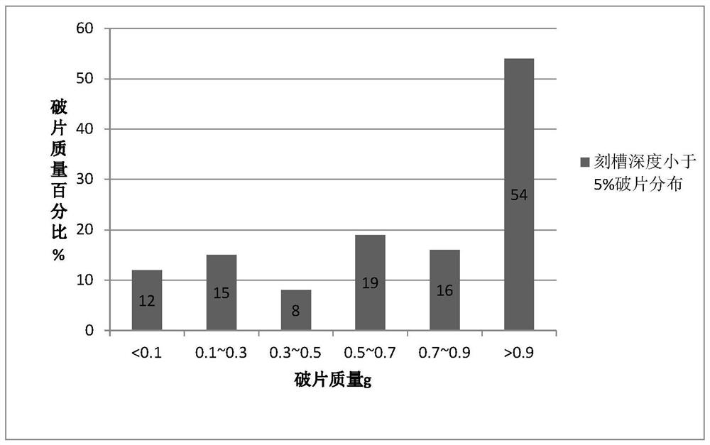
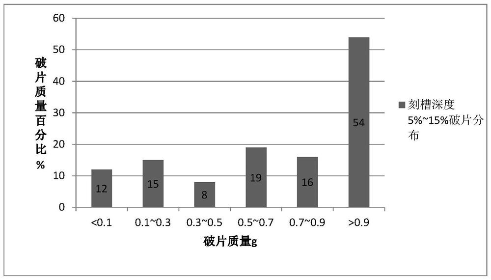
[0007] Aiming at the deficiencies of the prior art, the present invention provides a method for controlling the notched fragments of an electron beam projectile body, which uses the principle that the molten pool formed by the electron beam during the rapid movement process on the external surface of the projectile cannot be backfilled, and utilizes the rapid heating process at the bottom of the molten pool to The martensitic structure formed by rapid cooling in the high temperature zone enables the elastic body to obtain a good fragmentation control effect when the groove depth is greater than 5% and the wall thickness is less than 15%. The invention overcomes the low production efficiency existing in the prior art , High-hardness complex-shaped projectiles are difficult to process, poor process consistency, fragments connected, and projectile load-carrying capacity are low, providing a new technical approach for the prefabrication and processing of high-hardness, high-overload complex-shaped projectile fragments

Method used


Image

  • Electron beam projectile body grooving fragment control method
  • Electron beam projectile body grooving fragment control method
  • Electron beam projectile body grooving fragment control method

Examples


Embodiment 1

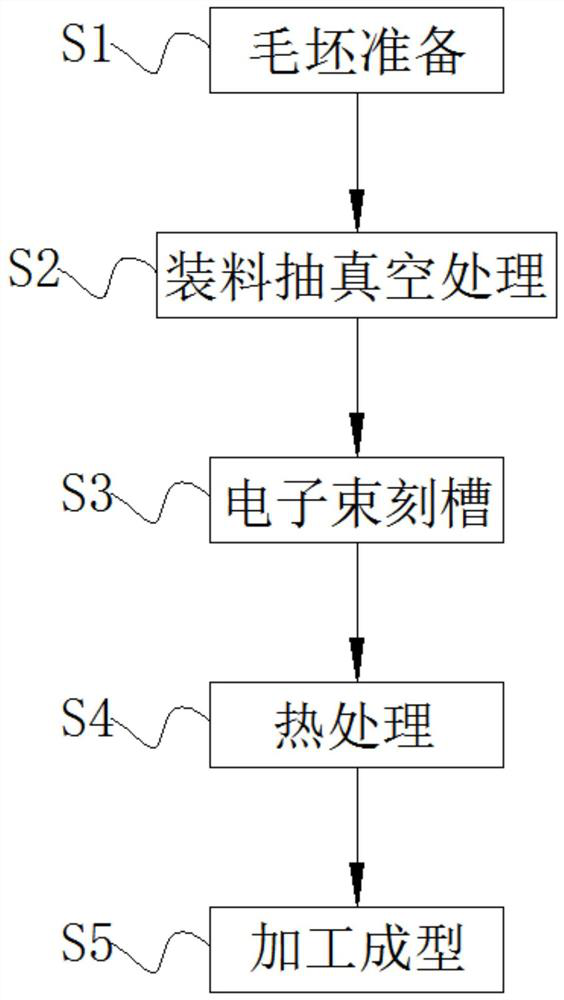
[0040] A method for controlling the notched fragments of an electron beam projectile body, specifically comprising the following steps:

[0041] S1. Blank preparation: According to the requirements of the actual ammunition drawings, use stamping equipment to process the blank of the projectile body, control the material within the specified hardness range through heat treatment, leave a margin of 0.5mm for rough machining of the projectile body, heat treatment temperature is 550°C, and the stamping equipment is modeled as MODEL stamping machine;

[0042] S2, charging and vacuuming treatment: insert the projectile blank in step S1 into the tooling of the electron beam equipment, and vacuumize, and the electron beam equipment is an electron beam welder whose model is THDW;

[0043] S3. Electron beam grooving: after the vacuuming in step S2 meets the requirements, start the body grooving program, and use electron beams to carve grooves on the outer surface of the projectile with ...

Embodiment 2

[0047] A method for controlling the notched fragments of an electron beam projectile body, specifically comprising the following steps:

[0048] S1. Blank preparation: According to the requirements of the live ammunition drawings, use stamping equipment to process the blank of the projectile body, control the material within the specified hardness range through heat treatment, leave a margin of 0.2mm for the rough machining of the projectile body, and heat treatment temperature is 500 ° C. The stamping equipment adopts the model of MODEL stamping machine;

[0049] S2, charging and vacuuming treatment: insert the projectile blank in step S1 into the tooling of the electron beam equipment, and vacuumize, and the electron beam equipment is an electron beam welder whose model is THDW;

[0050]S3. Electron beam grooving: When the vacuuming in step S2 meets the requirements, start the projectile body grooving program, and use electron beams to carve grooves on the outer surface of t...

Embodiment 3

[0054] A method for controlling the notched fragments of an electron beam projectile body, specifically comprising the following steps:

[0055] S1. Blank preparation: According to the requirements of the live ammunition drawing, use stamping equipment to process the blank of the projectile body, control the material within the specified hardness range through heat treatment, leave a margin of 1 mm for the rough machining of the projectile body, and heat treatment temperature is 650 ° C. The stamping equipment is MODEL punching machine;

[0056] S2, charging and vacuuming treatment: insert the projectile blank in step S1 into the tooling of the electron beam equipment, and vacuumize, and the electron beam equipment is an electron beam welder whose model is THDW;

[0057] S3. Electron beam grooving: when step S2 is vacuumed to meet the requirements, start the projectile body grooving program, and use electron beams to carve grooves on the outer surface of the projectile with a ...


PUM


Abstract

The invention discloses an electron beam projectile body grooving fragment control method. The method specifically comprises the following steps of S1, blank preparation, S2, charging and vacuumizing treatment, S3, electron beam grooving, S4, heat treatment and S5, machining and forming, and relates to the technical field of projectile body prefabricated fragment machining. According to the electron beam projectile body grooving fragment control method, the principle that a molten pool formed in the rapid moving process of an electron beam on the outer surface of a projectile body cannot be backfilled can be utilized, and a martensite structure formed by rapid cooling of a high-temperature area at the bottom of the molten pool in the rapid heating process is utilized; and fragments of the projectile body can be effectively controlled under the condition that the grooving depth is larger than 5% and smaller than 15% of the wall thickness, and the method is a production process which is high in production efficiency and suitable for high-hardness projectile bodies in complex shapes. Experimental results show that the technology can greatly improve the ammunition power and reduce the cost-efficiency ratio, and a new technical approach is provided for prefabrication of ammunition fragments such as high-overload small-caliber grenades and large-caliber grenades.

Description

technical field [0001] The invention relates to the technical field of projectile prefabricated fragment processing, in particular to an electron beam projectile notch fragment control method. Background technique [0002] Fragmentation ammunition breaks the body of the projectile through the explosion of the internal explosives, producing a large number of high-speed fragments to damage the target. In order to improve the power of ammunition, methods such as mechanical notching prefabricated fragments, stamping prefabricated fragments, and steel wire winding prefabricated fragments are usually used. [0003] The mechanical groove prefabricated fragment method uses a lathe to cut groove grids with a depth of more than 1 / 3 of the wall thickness on the surface of the projectile. Under the action of detonation waves, the projectile breaks along the root of the prefabricated groove to form control fragments. This method has low processing efficiency, The process stability is po...

Claims


Application Information

Patent Timeline
Patent Type & Authority Applications(China)
IPC IPC(8): B23P15/00
CPCB23P15/00
Inventor 刘雨竹白志超王辉朱锐
Owner 国基检测有限公司
Learn More