Substance identification apparatus and methods of using

Inactive Publication Date: 2010-04-01
MORPHO DETECTION INC
View PDF25 Cites 23 Cited by
  • Summary
  • Abstract
  • Description
  • Claims
  • Application Information

AI Technical Summary

Benefits of technology

[0011]Embodiments of the claimed invention are aimed at advantageously providing a more rapid method for performing a biological assay than the methods provided by prior portable detection systems.
[0012]Moreover, embodiments of the claimed invention are aimed at advantageously enabling multiple tests to be performed from a single test sample. This is a significant advantage when only a limited sample is available, and considering that sampling and dilution often constitute a significant fraction of a total assay time. Embodiments of the claimed invention allow the operator to run multiple assay tests with a single sampling step, greatly improving efficiency and potentially reducing the per-test cost of an assay.
[0013]Additionally, embodiments of the claimed invention simplify the sample collection, dilution, and assay steps by performing them in an integrated substance identification apparatus. Where applicable, one or more components of the integrate

Problems solved by technology

Such user-initiated activity is not well suited for use by first responders who often have limited mobility and dexterity (due to protective gear), limited visibility (due to face shields and eye protection), and limited time (often less than

Method used


Image

  • Substance identification apparatus and methods of using
  • Substance identification apparatus and methods of using
  • Substance identification apparatus and methods of using

Examples


first embodiment

PUSH & PULL

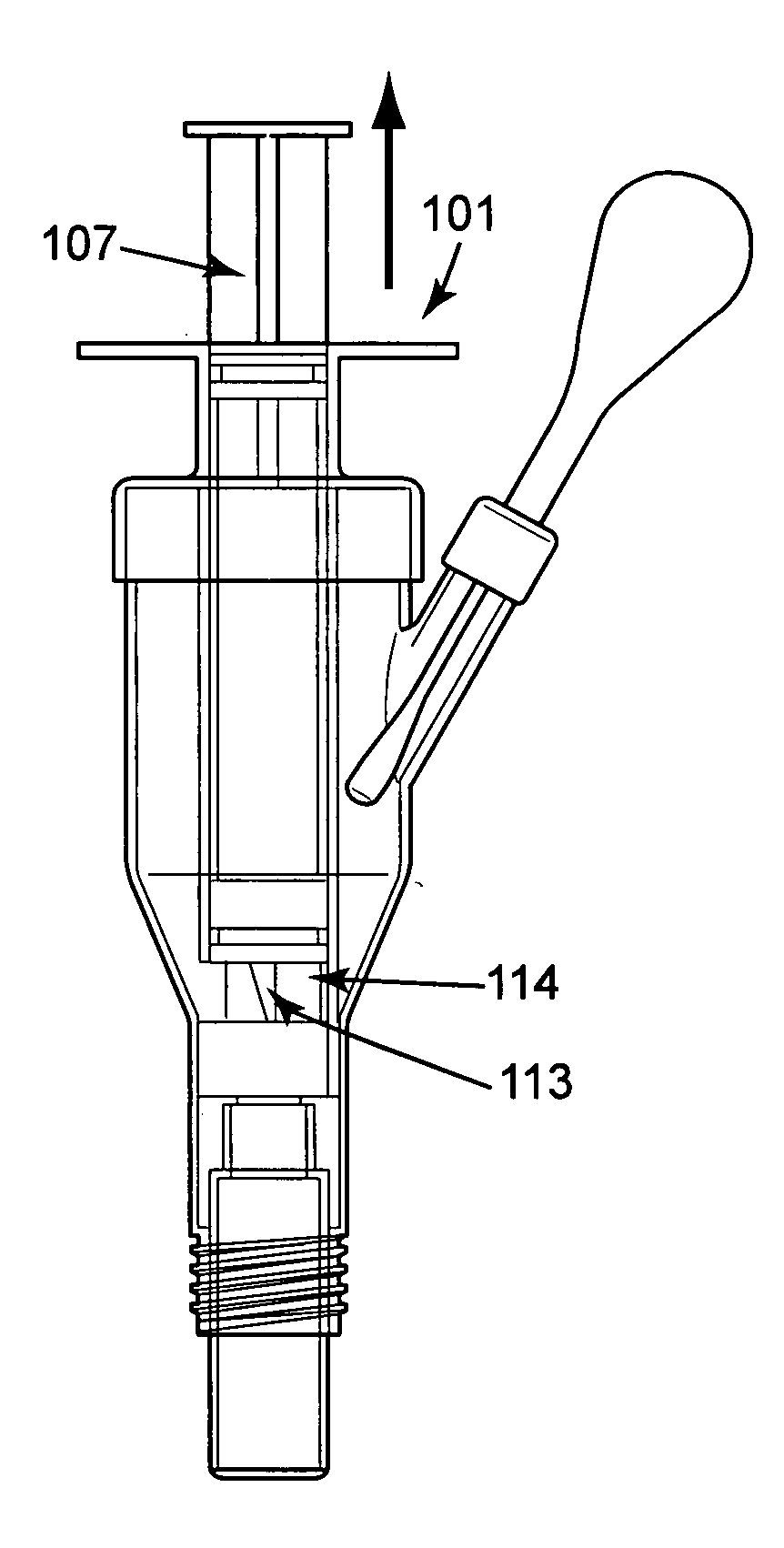
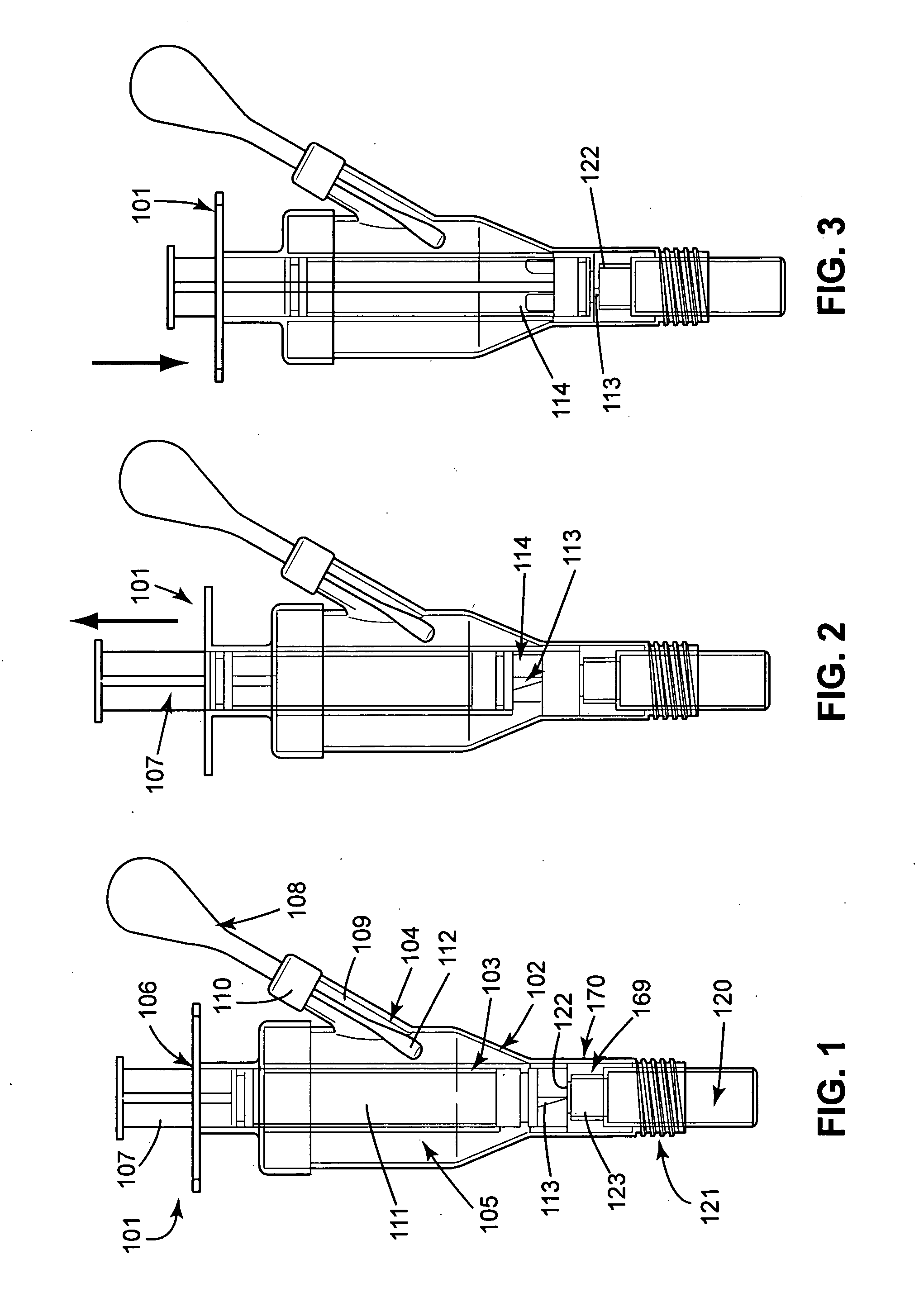
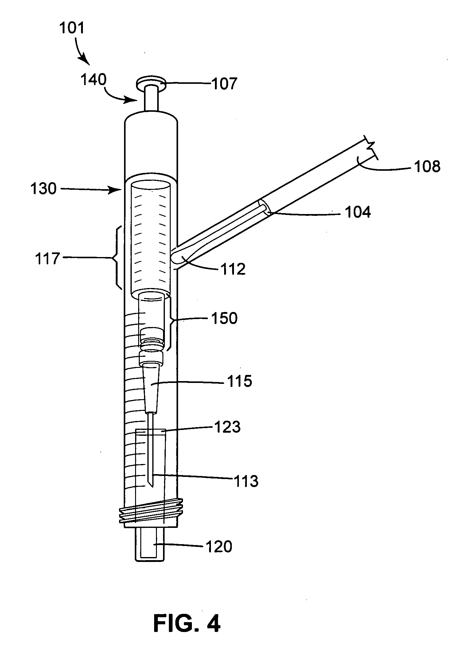
[0034]FIGS. 1, 2, and 3 are transparent side views of a first embodiment of a fluidics cartridge 101 configured to receive a container 120.

[0035]In this first embodiment, the fluidics cartridge 101 includes an outer chamber 102 and an inner chamber 103. FIGS. 1, 2, and 3 illustratively depict the outer chamber 102 and the inner chamber 103 as each having a cylindrical shape, but other shaped chambers can also be used—e.g. rectangular. A port 104 which may be oriented differently than shown in FIGS. 1, 2, and 3 is connected to the outer chamber 102. The port 104 includes a hollow bore 109 in communication with an interior of the outer chamber 102. The port 104 is thus configured to receive a sample collector 108. Non-limiting examples of a sample collector include a swab, a brush, cloth, etc. The outer chamber 102 stores a liquid medium 105), which may be a phosphate buffered saline solution. One or more access openings may be formed in a portion of the structure that defi...

second embodiment

PUSH

[0044]FIGS. 5 and 6 are cut-away side views of a second embodiment of a fluidics cartridge 101 configurable to receive a container 120. This second embodiment is similar to the first embodiment described above with reference to FIGS. 1, 2, and 3, with the following difference. As shown in FIG. 5, the plunger 107 is already retracted, with part of the liquid medium 105 (e.g., phosphate buffered saline solution) pre-stored in the interior of the outer chamber 102. Therefore, no “PULL” action is required. Instead, once the sample collector 108 is inserted into the port 104, as shown in FIGS. 5 and 6, and the liquid medium 105 is mixed with the sample—by shaking or other means, the plunger 107 is pushed to puncture a self-healing sealable member 122 seal (or septum), which may be attached to the cap 123, and inject the sample-laden liquid medium 105 into the container 120 (e.g., reaction chamber).

[0045]In passing, it is noted that the prototype apparatus of FIG. 4 may be adapted to ...


PUM


Abstract

A substance identification system comprises interrelated components. A fluidics cartridge is configured to permit suspension of a sample of a substance of interest in a liquid medium, and to permit transfer of the suspended sample into a container via syringe/needle action or other suitable actuation means. The container is configured to be fixedly or removably coupled with the fluidics cartridge. An interface cartridge is configured to position the container for analysis by a portable substance identification device.

Description

CROSS-REFERENCE TO RELATED APPLICATIONS[0001]This application claims the benefit under 35 U.S.C. §120 of the earlier filing date of co-pending U.S. Provisional Application Ser. No. 61 / 041,168, filed on Mar. 31, 2008, the entire contents of which are hereby incorporated by reference.BACKGROUND[0002]1. Field of the Invention[0003]The field of the invention generally relates to devices configured to detect chemical and biological threats, and more particularly to certain new and useful advances in portable substance identification devices of which the following is a specification, reference being had to the drawings accompanying and forming a part of the same.[0004]2. Discussion of Related Art[0005]A substance identification device is an apparatus configured to assay a sample using Raman Spectroscopy and / or other measurement techniques, to determine whether the sample contains one or more substances. Examples of substances include, but are not limited to, organic chemicals, inorganic c...

Claims


Application Information

Patent Timeline
IPC IPC(8): G01N1/10B01L3/02
CPCB01L3/0217B01L3/5029B01L3/545G01N2001/028B01L2300/022B01L2300/044B01L2400/0478B01L3/563
Inventor DORAISAMY, LOGANATHANBOBROFF, SERGEBURRELL, MICHAEL CRAIGFREEMAN, WALTER N.KUMAR, SANKARANMONDELLO, FRANK JOHNNAPOLI, JOSEPH DOMINICPAXON, TRACY LYNNSUTHERLAND, WILLIAM SCOTT
Owner MORPHO DETECTION INC
Why Eureka
Try Eureka