Separator

Inactive Publication Date: 2010-04-01
TOYOTA BOSHOKU KK
View PDF7 Cites 6 Cited by
  • Summary
  • Abstract
  • Description
  • Claims
  • Application Information

AI Technical Summary

Benefits of technology

[0017]In the separator according to the present embodiments, oil is heated instantaneously and locally by the heater before reaching the separation member, and thus gasification of fuel components is facilitated. The oil whose pressure is increased due to gasification of the fuel components, easily separates the fuel components through the separation member. The fuel components separated from the oil are discharged from the second area through the fuel outlet. The oil from which the fuel components have been separated is discharged from the first area through the oil outlet. As described above, heating the oil facilitates gasification of the fuel components. Further, gasification of the fuel components increases a pressure in a vicinity of the separation member, and thus allows the separation member to facilitate separation of the fuel components. In addition, the fuel components are separated from the locally heated oil by using the separation member. Unlike a conventional separator, the separator of the present embodiments requires no large heater and the like for heating oil as a whole, and thus can have a simple structure. In addition, since the oil only needs to be heated instantaneously and locally, no excessive heating is necessary to increase the temperature of the entire oil. Thus, oil deterioration due to heat can be prevented. Further, energy consumption can be limited compared to the conventional separator. Furthermore, an employed crossflow filtration method prevents solid components, such as sludge in the oil and the like, from depositing on a surface of the separation member and clogging the separation member, and thereby prevents a decline in performance of the separation member.
[0018]When the separator main body has a cylindrical shape, and the separation member has a cylindrical shape in the axial direction of the separator main body, the separator can have a further simple structure. In addition, when the first area is the area inside the separation member; the second area is the area outside the separation member; the oil inlet and the oil outlet are provided respectively to the both end surface portions of the separator main body; and the fuel outlet is provided to the side surface portion of the separator main body; an oil flow path is formed linearly from the oil inlet to the cylindrical

Problems solved by technology

In this case, however, a problem arise

Method used


Image

  • Separator
  • Separator
  • Separator

Examples


Example

First Embodiment

[0052](1) Structure of the Separator

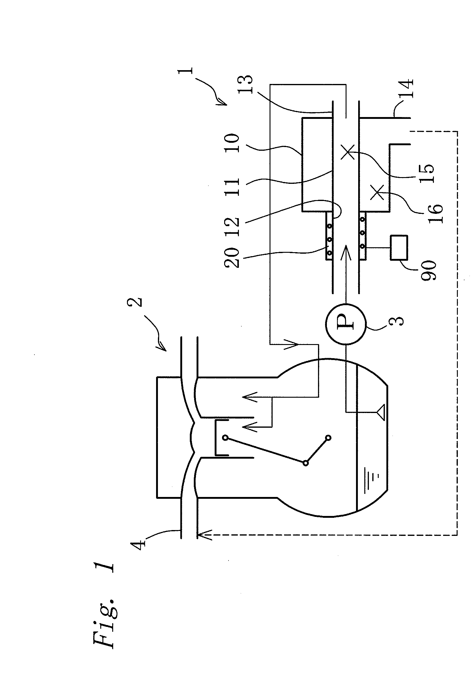
[0053]A separator 1 according to the first embodiment is provided on a discharge side of a lubrication pump 3, as shown in FIG. 1. The lubrication pump 3 in a lubricating circuit of a wet sump engine 2 (hereinafter simply referred to an “engine”) pumps oil to respective parts of the engine 2.

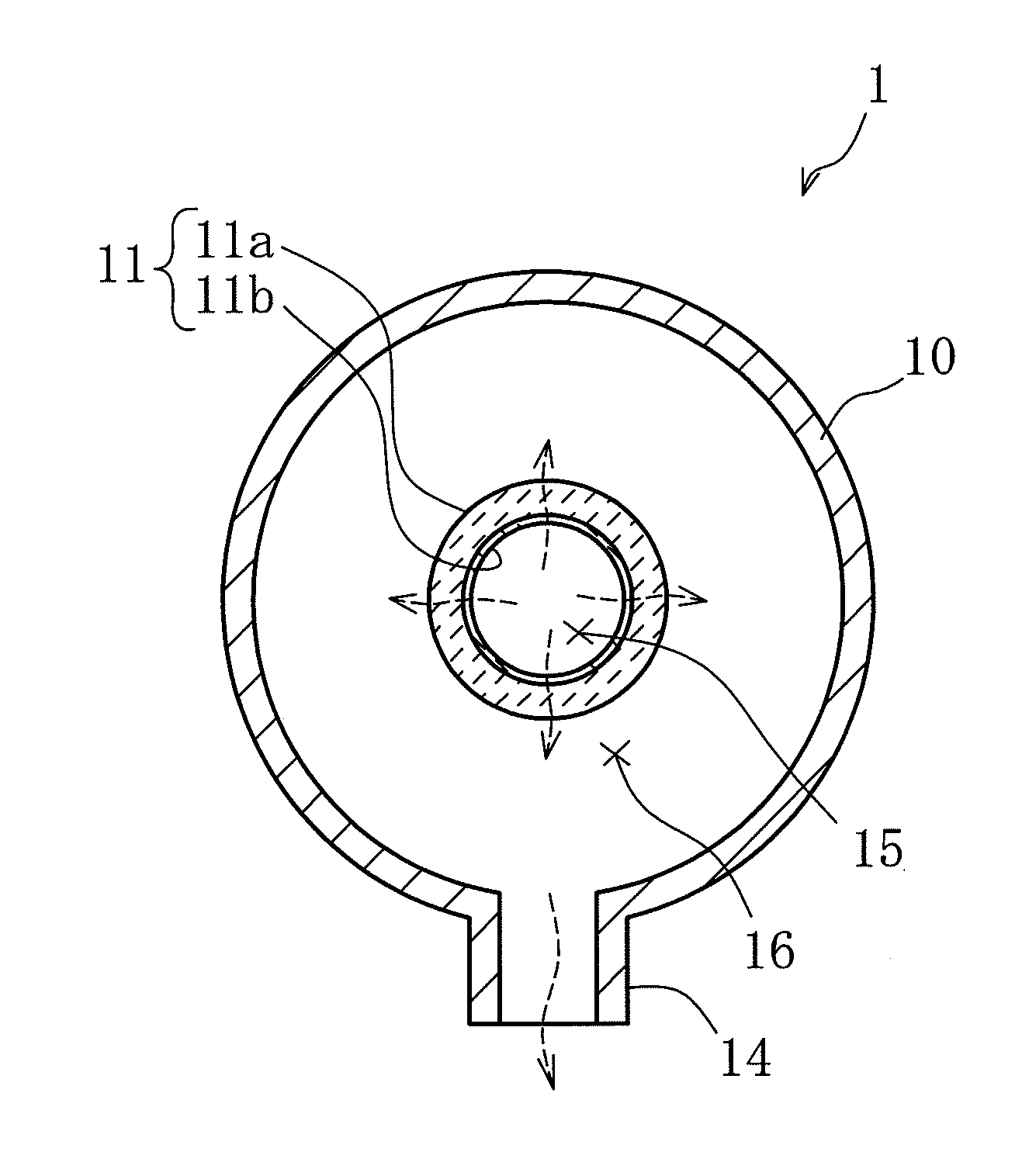
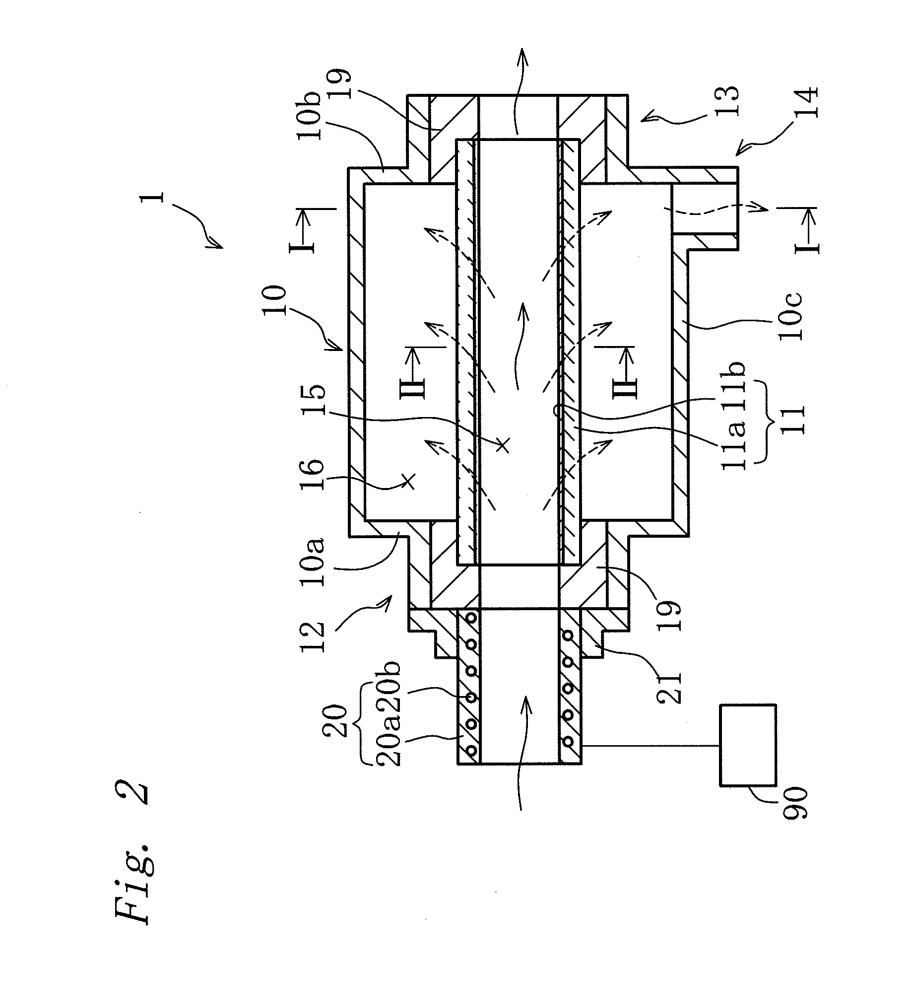
[0054]The separator 1 is provided with a cylindrical separator main body 10 formed from metal, as shown in FIGS. 2 and 3. A ceramic filter 11 (provided as an example of a separation member of the present invention) is provided inside the separator main body 10. Both end portions of the ceramic filter 11 are attached to both end surface portions 10a and 10b of the separator main body 10 by way of ring members 19 having stepped holes. An inside of the separator main body 10 is partitioned by the ceramic filter 11, into a first area 15 inside the ceramic filter 11 and a second area 16 outside the ceramic filter 11. Further, an oil inlet 12 is prov...

Example

Second Embodiment

[0063]A separator according to the second embodiment is explained below. In the separator according to the second embodiment, same reference numerals are provided to components substantially the same as the separator 1 of the above-described first embodiment, and detailed explanations of the components are omitted. Similar to the above-described first embodiment, a separator 1 according to the second embodiment is provided on a discharge side of a lubrication pump 3. The lubrication pump 3 pumps oil in a lubricating circuit of an engine 2 to respective parts of the engine 2.

[0064](1) Structure of the Separator

[0065]The separator 1 according to the second embodiment is provided, as shown in FIG. 5, with a cylindrical separator main body 10 having an oil inlet 32 feeding oil to inside and an oil outlet 33 discharging the oil. A cylindrical ceramic filter 31 is provided inside the separator main body 10. An inside of the separator main body 10 is partitioned by the cer...

Example

Third Embodiment

[0075]A separator according to the third embodiment is explained below. In the separator according to the third embodiment, same reference numerals are provided to components substantially the same as the separator 1 of the above-described first embodiment, and detailed explanations of the components are omitted. Similar to the above-described first embodiment, a separator 1 according to the third embodiment is provided on a discharge side of a lubrication pump 3. The lubrication pump 3 pumps oil in a lubricating circuit of an engine 2 to respective parts of the engine 2.

[0076](1) Structure of the Separator

[0077]The separator 1 according to the third embodiment is provided with a ceramic filter 81. As shown in FIGS. 6 and 7, both end portions of the ceramic filter 81 are attached to an end surface portion 10a of a separator main body 10 by way of a lid member 22 and to an end surface portion 10b by way of a ring member 19 having a stepped hole. An inside of the separ...


PUM

PropertyMeasurementUnit
Temperatureaaaaaaaaaa
Diameteraaaaaaaaaa
Shapeaaaaaaaaaa

Abstract

A separator separates fuel components from oil diluted by fuel in a crossflow filtration method. The separator includes a tubular separator main body; a separation member provided in the separator main body to partition an inside of the separator main body into a first area and a second area, and further to allow the fuel components contained in the oil to permeate and thus separate the fuel components; an oil inlet provided to the separator main body and feeding the oil to the first area; an oil outlet provided to the separator main body and discharging the oil from the first area; a fuel outlet provided to the separator main body and discharging the fuel components from the second area; and a heater provided to an upstream side of the separation member and heating the oil before the oil reaches the separation member.

Description

CROSS-REFERENCE TO RELATED APPLICATIONS[0001]The present application claims priority under 35 U.S.C. §119 of Japanese Application No. 2008-251544 filed on Sep. 29, 2008, the disclosure of which is expressly incorporated by reference herein in its entirety.BACKGROUND OF THE INVENTION[0002]1. Field of the Invention[0003]The present invention relates to a separator, more specifically to a simple-structured separator capable of separating fuel components mixed into lubricating oil for an internal combustion engine, without deteriorating the oil.[0004]2. Description of Related Art[0005]In order to prevent dilution of lubricating oil for an internal combustion engine caused by mixed fuel components, a conventionally known separation method is to increase temperature of the oil so as to gasify and separate the fuel components (refer to Related Arts 1 and 2, for example). It is disclosed in Related Art 1 above that an oil heater provided in a lubricating circuit of an internal combustion en...

Claims


Application Information

Patent Timeline
IPC IPC(8): B01D35/18B01D21/30
CPCB01D21/0012B01D63/06B01D71/024B01D2311/103B01D2313/22B01D2321/2025B01D21/267C10M175/06F01M11/03F01M2011/033C10M175/0058B01D21/26
Inventor SAITO, YASUHIRO
Owner TOYOTA BOSHOKU KK
Why Eureka
Try Eureka