Light emitting device and method of manufacturing the same

a technology of light emitting devices and manufacturing methods, which is applied in the manufacture of electric discharge tubes/lamps, cold cathode manufacturing, and electromechanical systems, etc., can solve the problems of increasing the cost of products, and increasing the number of manufacturing steps. , to achieve the effect of reliable light emitting and simple manufacturing method

Inactive Publication Date: 2010-04-01
SEIKO INSTR INC
View PDF9 Cites 23 Cited by
  • Summary
  • Abstract
  • Description
  • Claims
  • Application Information

AI Technical Summary

Benefits of technology

[0015]According to the present invention, a reliable light emit

Problems solved by technology

However, the LED element alone is still weaker in luminance than other light emitters, and hence a large number of the LED elements have to be combined to constitute a light emitter.
However, the LED element generates heat each time the LED element emits light, and hence heat expansion and contraction repeatedly

Method used


Image

  • Light emitting device and method of manufacturing the same
  • Light emitting device and method of manufacturing the same
  • Light emitting device and method of manufacturing the same

Examples


Embodiment Construction

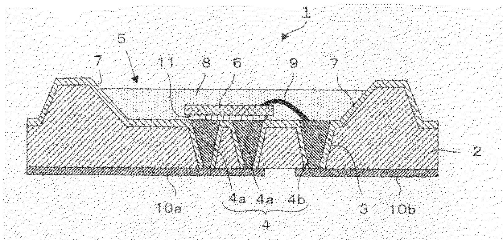
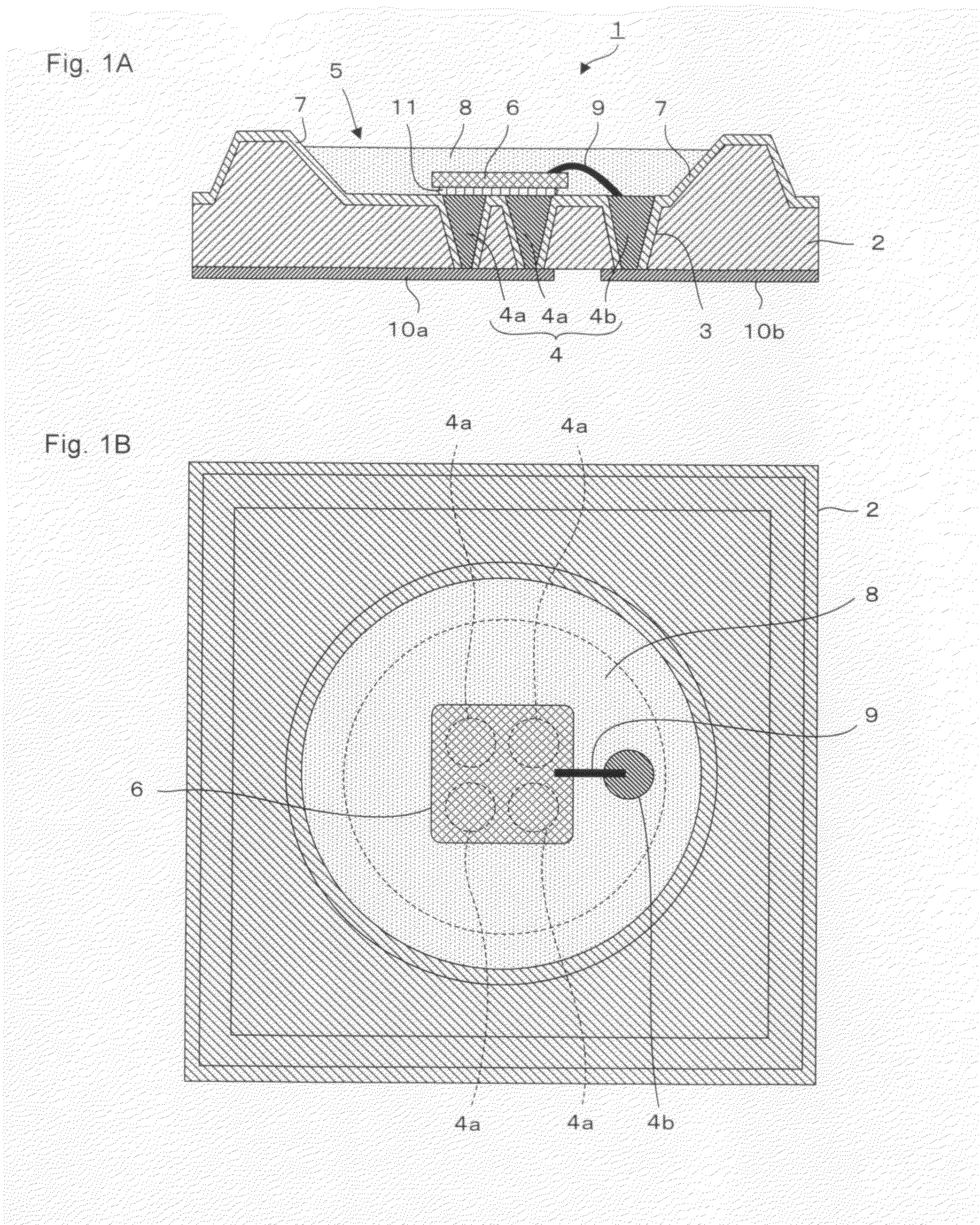
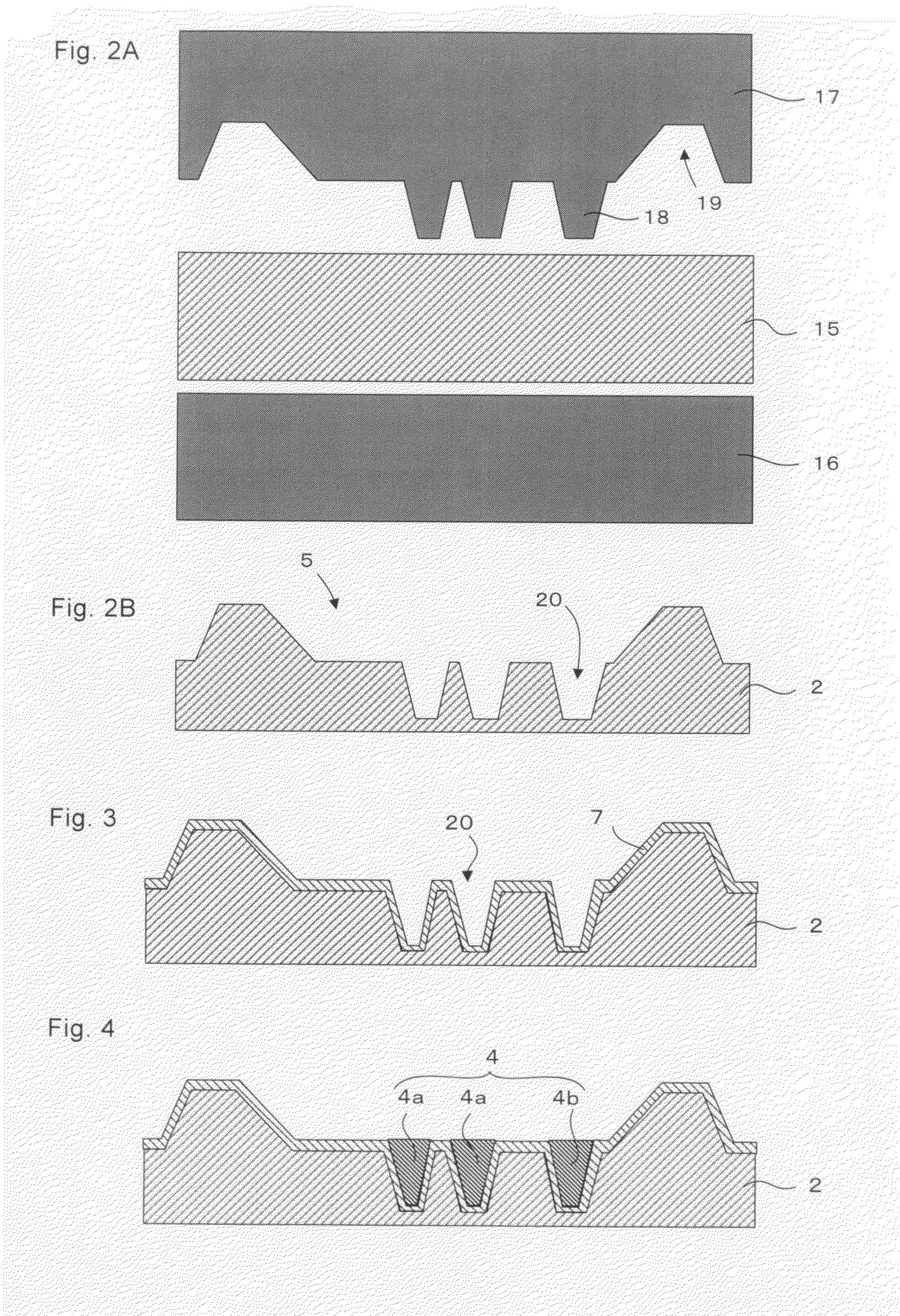
[0028]A light emitting device according to the present invention includes a glass substrate in which a recess is formed, and an insulating reflective film is formed on an inner wall surface and a bottom surface of the recess. Further, a through hole is formed at the bottom of the recess, and a through-hole electrode formed of a conductive material is formed in the through hole. A light emitting diode element is mounted on the through-hole electrode. The light emitting diode element is received in the recess of the glass substrate and sealed by a sealing material supplied to the recess. The glass substrate is integrally formed of a glass material and has no bonding surface. Therefore, even when expansion and contraction are repeated due to heat generated in the light emitting diode element, moisture and foreign substances hardly enter from the outside. This suppresses corrosion of the electrode material and deterioration of characteristics of the light emitting diode element to impro...


PUM


Abstract

A light emitting device includes: a glass package (2) having a recess (5) in its center; a through-hole electrode (4) formed by filling a through hole (3), which is formed at a bottom of the recess (5), with a conductive material; a light emitting diode element (6) received in the recess (5) and mounted on the through-hole electrode (4); an insulating multilayer interference film (7) formed on an inner wall surface and a bottom surface of the recess (5); and a sealing material for sealing the light emitting diode element. With this structure, the light emitting device is improved in reliability.

Description

BACKGROUND OF THE INVENTION[0001]1. Field of the Invention[0002]The present invention relates to a light emitting device having a structure in which a light emitting element is packaged, and a method of manufacturing the light emitting device.[0003]2. Description of the Related Art[0004]In recent years, a light emitting diode element (hereinafter referred to as LED element) has been improved in luminance and the like, and is put into practical use in a variety of fields. For example, the LED element is used for a backlight of a liquid crystal display apparatus, a light emitting element of a traffic light, an electric bulletin board, and other illumination purposes. The LED element may be operated with low voltage and low power consumption, and has been improved in luminance. Therefore, the LED element is expected to be applied to an indoor light, automobile illumination, and the like.[0005]However, the LED element alone is still weaker in luminance than other light emitters, and hen...

Claims


Application Information

Patent Timeline
IPC IPC(8): H01K1/30H01J9/00
CPCH01L33/486H01L33/62H01L33/647H01L2224/48091H01L2924/10253H01L2224/45144H01L2924/00014H01L2924/00H01L2924/181H01L2224/73265H01L2924/15174H01L2924/00012
Inventor KAMAMORI, HITOSHIOKU, SADAOHAYASHI, KEIICHIRO
Owner SEIKO INSTR INC
Why Eureka
Try Eureka