Battery unit and battery system using the battery unit

Active Publication Date: 2010-04-01
KK TOSHIBA
View PDF2 Cites 45 Cited by
  • Summary
  • Abstract
  • Description
  • Claims
  • Application Information

AI Technical Summary

Benefits of technology

[0011]With such a configuration, even in the case where a part of the battery arms included in the battery unit is isolated by the switches in response to the occurrence of the abnormality in the batteries, the charge/discharge current or the charge/discharge power, which flows through the battery unit, is reduced step by step in response to the number of the isolated battery arms, whereby the overcurrent of the charge/discharge current flowing through the battery arms is prevented. Therefore, even after the switches are opened, the battery unit can continue the operation thereof.
[0012]Alternatively, in the battery system according to the first aspect of the present invention, in the case of having received the switch opening signals from the battery unit, the charge/discharge control device may perform the control to reduce the charge/discharge current or charge/discharge powe

Problems solved by technology

As a result, there has been a problem that battery cells turn to an over discharge state and to a reve

Method used


Image

  • Battery unit and battery system using the battery unit
  • Battery unit and battery system using the battery unit
  • Battery unit and battery system using the battery unit

Examples


embodiment 1

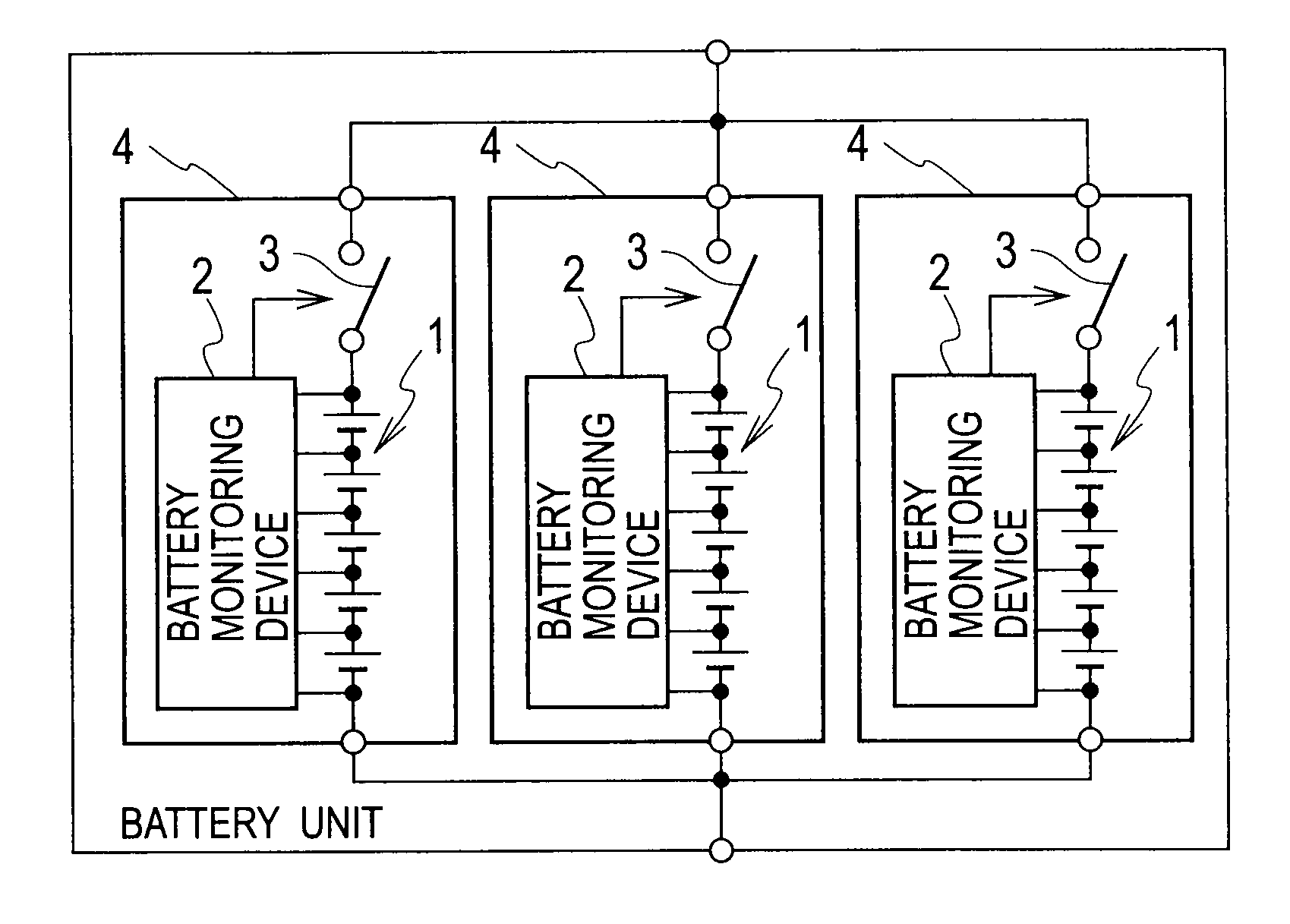
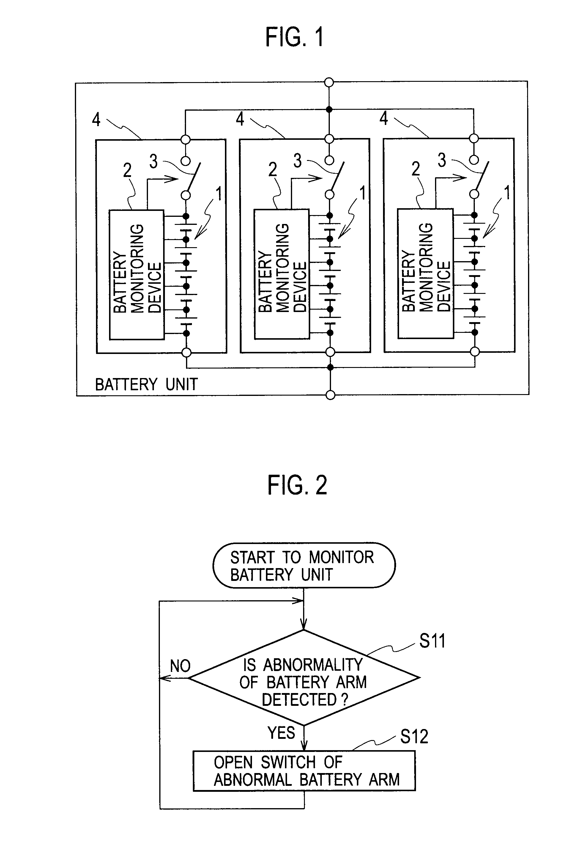
[0039]A battery unit according to Embodiment 1 of the present invention, which is shown in FIG. 1, is composed in such a manner that battery arms 4 (three pieces in the example shown in FIG. 1) are connected in parallel in order to increase a battery capacity. Each of the battery arms 4 includes a battery 1, a battery monitoring device 2, and a switch 3.

[0040]The battery 1 is configured of battery cells composed of secondary batteries such as lithium-ion batteries and nickel-hydrogen batteries. Since the single battery cell has limitations in energy capacity and output voltage, the battery 1 is configured in such a manner that the battery cells are connected in series. In such a way, in the battery 1, the output voltage and the energy capacity are increased.

[0041]The battery monitoring device 2 is connected to a positive electrode and negative electrode of each of the battery cells composing the battery 1, and detects a battery voltage, a battery temperature and the like of each of ...

embodiment 2

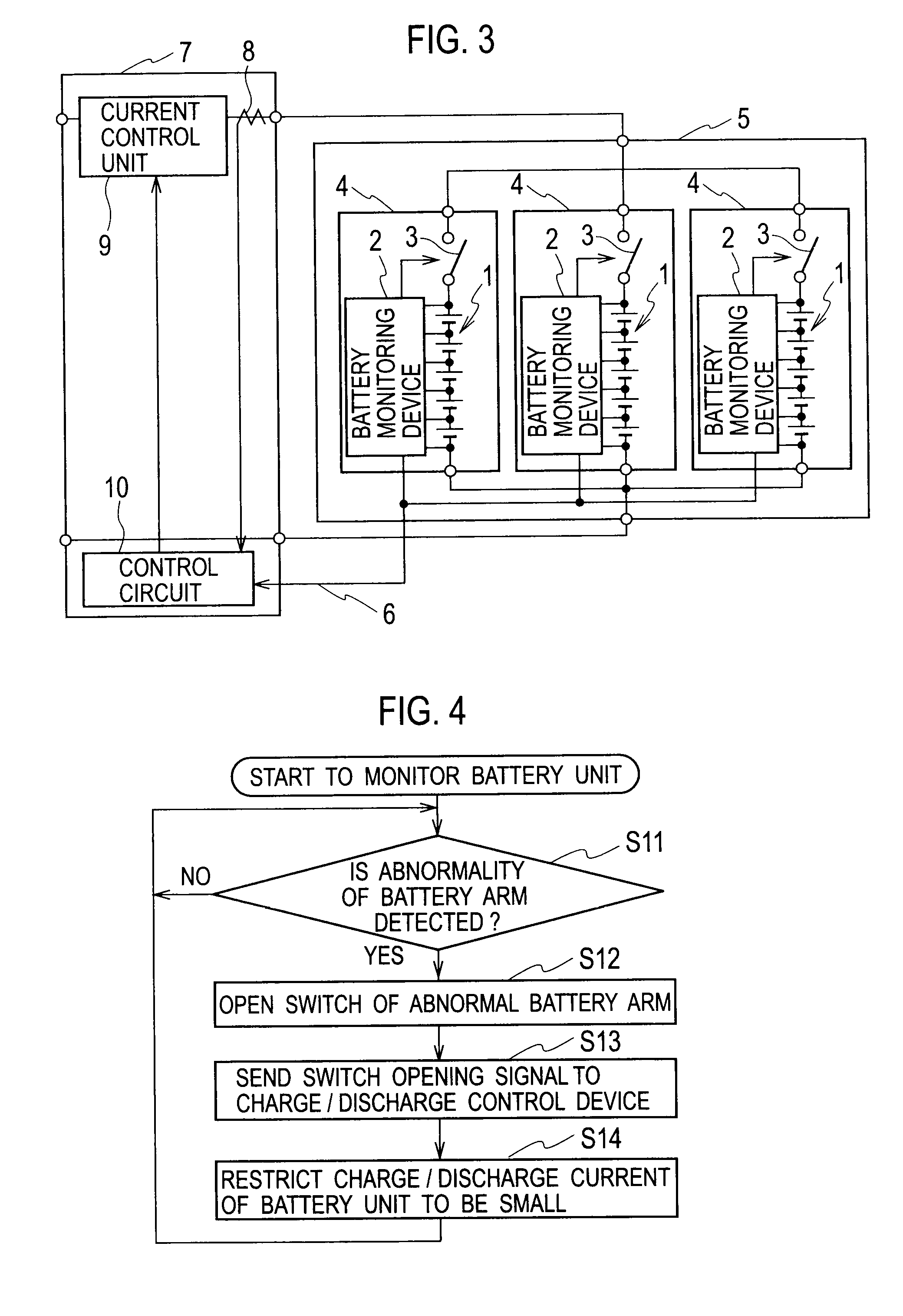
[0046]A battery system according to Embodiment 2 of the present invention, which is shown in FIG. 3, includes a battery unit 5, and a charge / discharge control device 7. The battery unit 5 is composed by adding the following function to the battery unit according to Embodiment 1 described above. Specifically, in the case of having sent the control signal to the switch 3 and having opened the switch 3 concerned, each of the battery monitoring devices 2 of the battery unit 5 sends a switch opening signal, which indicates that the switch 3 has been opened, to the charge / discharge control device 7 through a communication channel 6. Note that the battery unit 5 is the same as the battery unit according to Embodiment 1 except the above-described point. Accordingly, the same reference numerals are assigned to the same constituents as those used in FIG. 1, and a description thereof will be omitted.

[0047]The charge / discharge control device 7 includes a current detector 8, a current control un...

embodiment 3

[0054]In the case of having received the switch opening signals sent from the battery unit 5, a battery system according to Embodiment 3 of the present invention reduces the current value of the charge / discharge current step by step in response to the number of the switch opening signals. A configuration of the battery system according to Embodiment 3 is the same as the configuration of the battery system according to Embodiment 2, which is shown in FIG. 3, except the function of the control circuit 10.

[0055]In the case of having received the switch opening signals sent from the battery unit 5 through the communication channel 6, the control circuit 10 decides the upper limit value of the charge / discharge current, which should flow between the charge / discharge control device 7 and the battery unit 5, at a current value that becomes smaller step by step from the upper limit value of the charge / discharge current of the case where the battery unit 5 is normal in accordance with an incr...


PUM


Abstract

A battery system includes a battery unit in which battery arms are connected in parallel, and a charge/discharge control device that controls charge/discharge of the battery unit. Each of the battery arms includes: a battery composed of one or more battery cells connected in series; a switch connected in series to the battery; and a battery monitoring device that, in a case of having detected abnormality of the battery, opens the switch to thereby isolate the battery arm including the abnormal battery, and sends a switch opening signal indicating that the switch has been opened to the charge/discharge control device. The charge/discharge control device performs a control to reduce a charge/discharge current or charge/discharge power of the battery unit when the switch opening signal is sent from the battery monitoring device of the battery unit to the charge/discharge control device.

Description

BACKGROUND OF THE INVENTION[0001]1. Field of the Invention[0002]The present invention relates to a battery unit in which battery arms are connected in parallel, and to a battery system using the battery unit.[0003]2. Description of the Related Art[0004]In a conventional battery system, a battery charge / discharge switching method has been known, which is capable of achieving reduction in size, weight and cost by omitting or downsizing a cooling device while reducing a conduction loss to a semiconductor switch, and is capable of eliminating an occurrence of mechanical abrasion or operation sounds, which follow frequent on / off operations of a mechanical contact switch (refer to Japanese Patent Laid-Open Publication No. 2007-110887 as Patent Publication 1).[0005]In this battery charge / discharge switching method, a charge / discharge switching circuit in which the mechanical contact switch, the semiconductor switch and a diode are connected in parallel is connected in series to each of bat...

Claims


Application Information

Patent Timeline
IPC IPC(8): H02J7/00H01M50/502H01M50/572
CPCH02J7/0026H01M10/48H02J7/0014Y02E60/10H02J7/00304
Inventor MONDEN, YUKITAKAMORIKAWA, RYUICHIMIZUTANI, MAMIKUWANO, YUKIKUBOTA, MASAYUKIITO, YASUYUKI
Owner KK TOSHIBA
Why Eureka
Try Eureka