Liquid crystal device and electronic apparatus

a liquid crystal device and electronic equipment technology, applied in non-linear optics, instruments, optics, etc., can solve the problems of deterioration of reliability, liquid crystal display irregularities, and liquid crystal device damage, and achieve high-quality images

Active Publication Date: 2010-04-01
JAPAN DISPLAY WEST
View PDF4 Cites 12 Cited by
  • Summary
  • Abstract
  • Description
  • Claims
  • Application Information

AI Technical Summary

Benefits of technology

[0022]According to such a configuration, it is possible to provide an electronic apparatus having the liquid crystal device free fro

Problems solved by technology

For this reason, there is a problem in terms of display quality in that such a liquid crystal device is likely to be affected by external electric fields outside of the counter substrate, typically static electricity, and thus, irregularities in liquid crystal display are likely to occur.
However, since adhesion is poor between metal materials or metal oxides and curable resin, which is the forming m

Method used


Image

  • Liquid crystal device and electronic apparatus
  • Liquid crystal device and electronic apparatus
  • Liquid crystal device and electronic apparatus

Examples


first embodiment

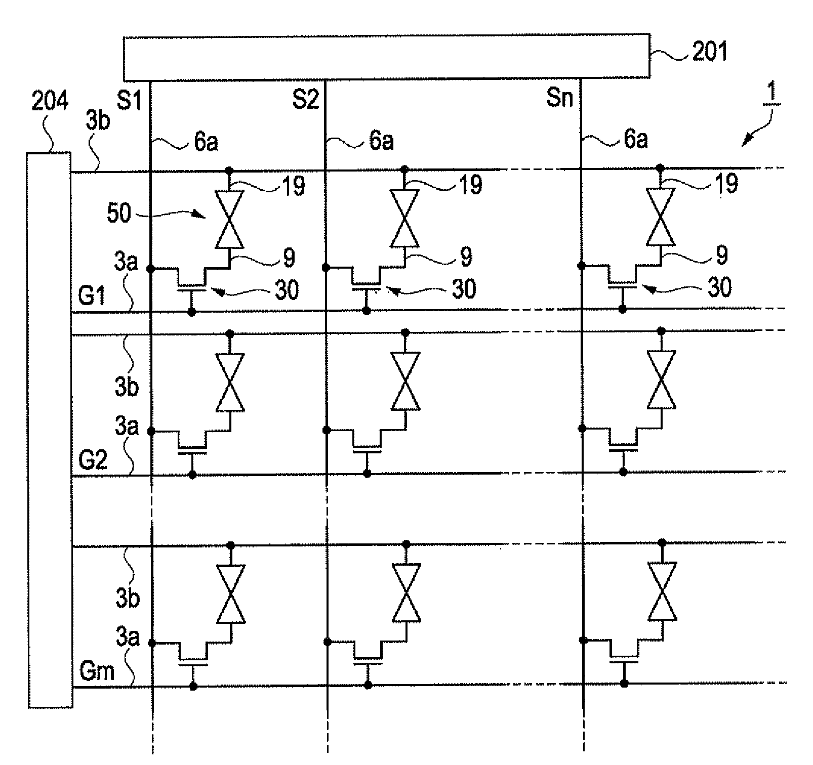
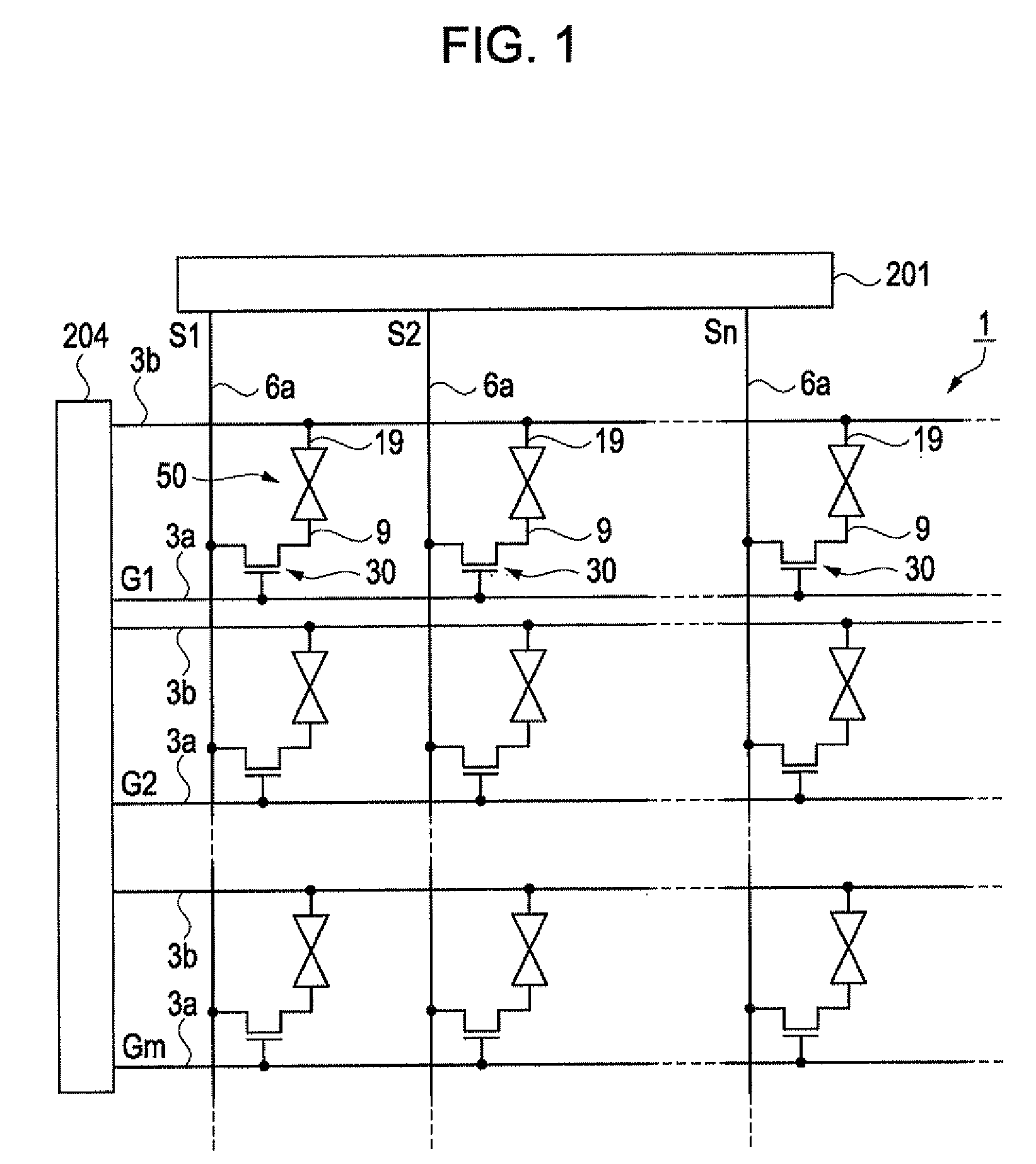
[0033]A liquid crystal device 1 according to a first embodiment of the invention will be described herein below with reference to FIGS. 1 to 5. In the drawings below, individual members are appropriately depicted with different thicknesses and measurements in order to make them recognizable in the drawings.

[0034]The liquid crystal device according to the present embodiment displays images by controlling the azimuth angle of liquid crystal molecules by using a lateral electric field perpendicular to the light traveling direction. An IPS (In-Plane Switching) mode and an FFS (Fringe-Field Switching) mode are known as examples of such a lateral electric field mode. Although the descriptions below are based on a liquid crystal device capable of performing full-color display in liquid crystal devices employing an FFS mode driving method, the invention can be equally applied to an IPS mode liquid crystal device.

[0035]FIG. 1 is an equivalent circuit diagram of a liquid crystal device 1 acco...

second embodiment

[0078]Next, a liquid crystal device 2 according to a second embodiment of the invention will be described. FIG. 6 is a simplified cross-sectional view of the liquid crystal device 2 according to the second embodiment of the invention, which corresponds to FIG. 5 in the first embodiment. Therefore, the configurations of the non-display area are not illustrated.

[0079]The liquid crystal device 2 according to the present embodiment has a similar configuration to the liquid crystal device 1 according to the first embodiment, except that the light shielding layer 22b, the coloring layer 22a, and the electrostatic shielding layer 40 are arranged differently on the counter substrate 20. In the descriptions of the present embodiment, drawings corresponding to FIGS. 1 to 4 are omitted. For the same reason, the respective elements formed on the element substrate body 11, such as TFTs 30, will be omitted, and only the element substrate 10 will be illustrated.

[0080]As illustrated in the drawing,...

third embodiment

[0085]Next, a liquid crystal device 3 according to a third embodiment of the invention will be described. FIG. 7 is a simplified cross-sectional view of the liquid crystal device 3 according to the third embodiment of the invention, which corresponds to FIG. 6 in the second embodiment. The liquid crystal device 3 according to the present embodiment has a similar configuration to the liquid crystal device 2 according to the second embodiment, except that the light shielding layer 22b, the coloring layer 22a, and the electrostatic shielding layer 40 are arranged differently on the counter substrate 20. Therefore, in the description of the present embodiment, drawings corresponding to FIGS. 1 to 4 are omitted, and the respective elements formed on the element substrate body 11, such as TFTs 30, will be omitted.

[0086]As illustrated in the drawing, in the color filter layer 22, the coloring layer 22a is thicker than the light shielding layer 22b, and a portion of the peripheral edge of t...


PUM


Abstract

A lateral electric field mode liquid crystal device comprising: a first substrate having pixel electrodes and common electrodes which are provided on one surface thereof; a second substrate disposed so as to face that surface of the first substrate with a predetermined distance therebetween; a liquid crystal layer sandwiched between the first substrate and the second substrate; and a loop-shaped sealing member disposed so as to surround the liquid crystal layer, with the liquid crystal device driving the liquid crystal layer by an electric field generated between the pixel electrodes and the common electrodes.

Description

BACKGROUND[0001]1. Technical Field[0002]The present invention relates to a liquid crystal device and an electronic apparatus.[0003]2. Related Art[0004]As a means for achieving a wide viewing angle of a liquid crystal device, an IPS (In-Plane Switching) mode, which is one example of a so-called lateral electric field mode, has been put into practical use, in which an electric field is generated in an in-plane direction (lateral direction) to a substrate, the lateral electric field causes liquid crystal molecules contained in a liquid crystal layer to be rotated in a plane parallel of the substrate, thus controlling the transmission of light. Further, an FFS (Fringe-Field Switching) mode is proposed as an improvement of the IPS mode.[0005]Such a lateral electric field mode liquid crystal device has a configuration in which electrodes such as common electrodes and pixel electrodes or conductive members such as wirings are arranged on an element substrate having formed thereon driving e...

Claims


Application Information

Patent Timeline
IPC IPC(8): G02F1/1333
CPCG02F1/134363G02F1/1339
Inventor YOSHIDA, SHUHEITANAKA, SHINICHIRO
Owner JAPAN DISPLAY WEST
Why Eureka
Try Eureka