Power conversion system and method for active damping of common mode resonance

a power conversion system and common mode technology, applied in the direction of control system, conversion with intermediate conversion to dc, electric power transfer ac network, etc., can solve the problems of motor failure, high peak voltage or magnetic saturation in choke choke, capacitor components, insulation or thermal failure,

Active Publication Date: 2010-04-01
ROCKWELL AUTOMATION TECH
View PDF8 Cites 75 Cited by
  • Summary
  • Abstract
  • Description
  • Claims
  • Application Information

AI Technical Summary

Benefits of technology

[0008]Further aspects of the disclosure relate to a method of damping common mode resonance in a power converter. The method includes generating switching control signals according to a desired power converter output, operating inverter or rectifier switching devices according to the control signals to convert DC electrical power to output power or vice versa, and measuring feedback value(s) indicative of one or more electrical conditions at a converter input, a converter DC circuit, and/or a converter output. The method further includes calculating a damping resistance current value associated with a predetermined virtual damping resistance value in parallel with the output or input capacitor(s) based at least partially on a measured output or input voltage value, and selectively modifying the switching control signals according to the calculated damping resistance current value. The switching control signal generation in certain embodiments may include providing at least one reference stator current value based at least partially on at least one feedback value and on the at least one setpoint, providing at least one output capacitor current value based at least partially on the at least one feedback value and on at least one predetermined output capacitance value, and generating at least one offset inverter current value based at least partially on the reference stator and output capacitor current values. The switching signal modification may include providing the damping resistance current value according to the virtual damping resistance value and the measured output or input voltage value, and generating a damping compensated inverter or rectifier current value based at least partially o

Problems solved by technology

High common mode voltages can damage converter components and may cause motor failure because of insulation failure or bearing currents.
However, the energy storage components in the common mode loop form a resonance, which can be excited by the back emf of the motor operating at certain speeds leading t

Method used


Image

  • Power conversion system and method for active damping of common mode resonance
  • Power conversion system and method for active damping of common mode resonance
  • Power conversion system and method for active damping of common mode resonance

Examples


Embodiment Construction

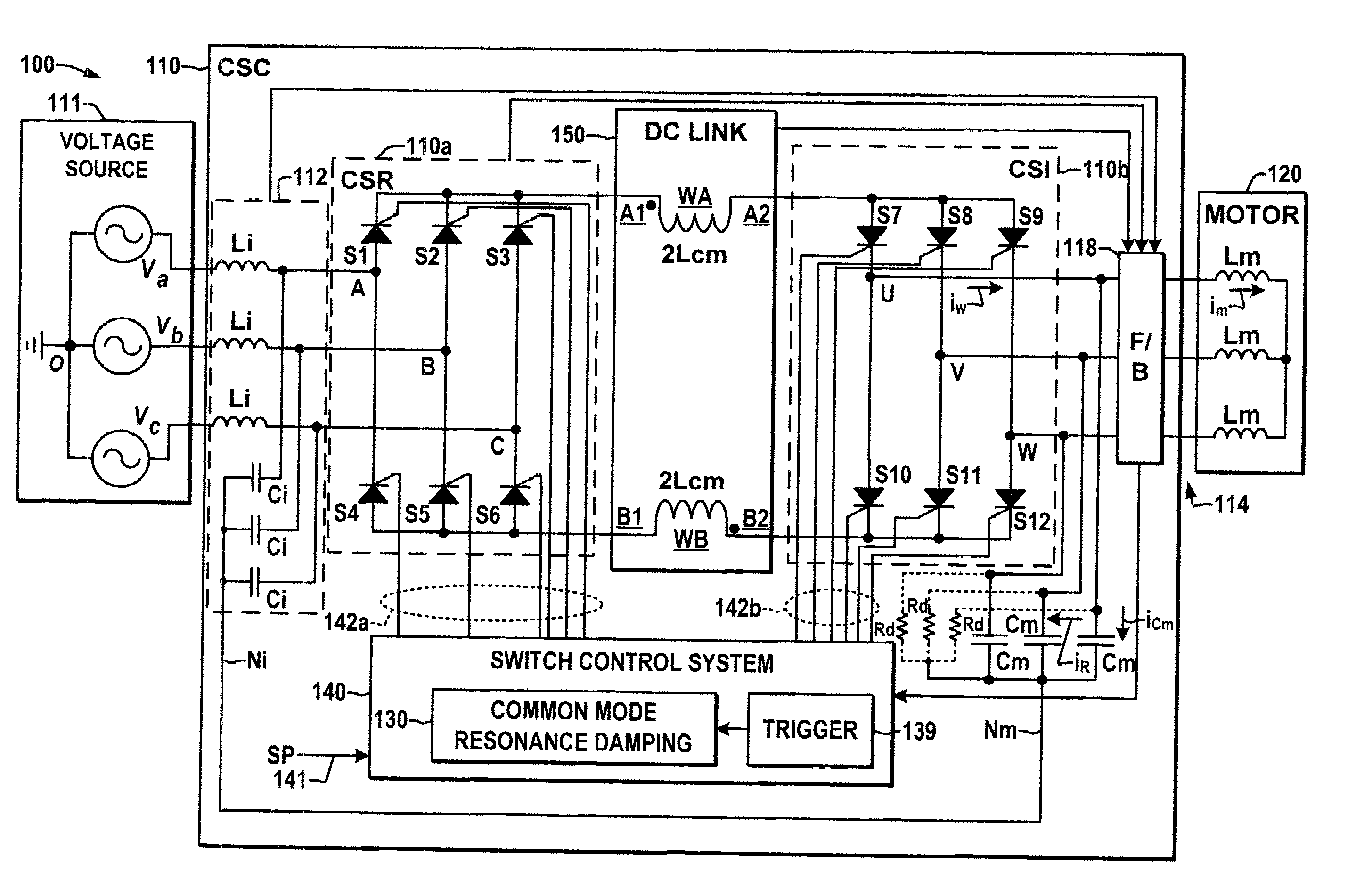
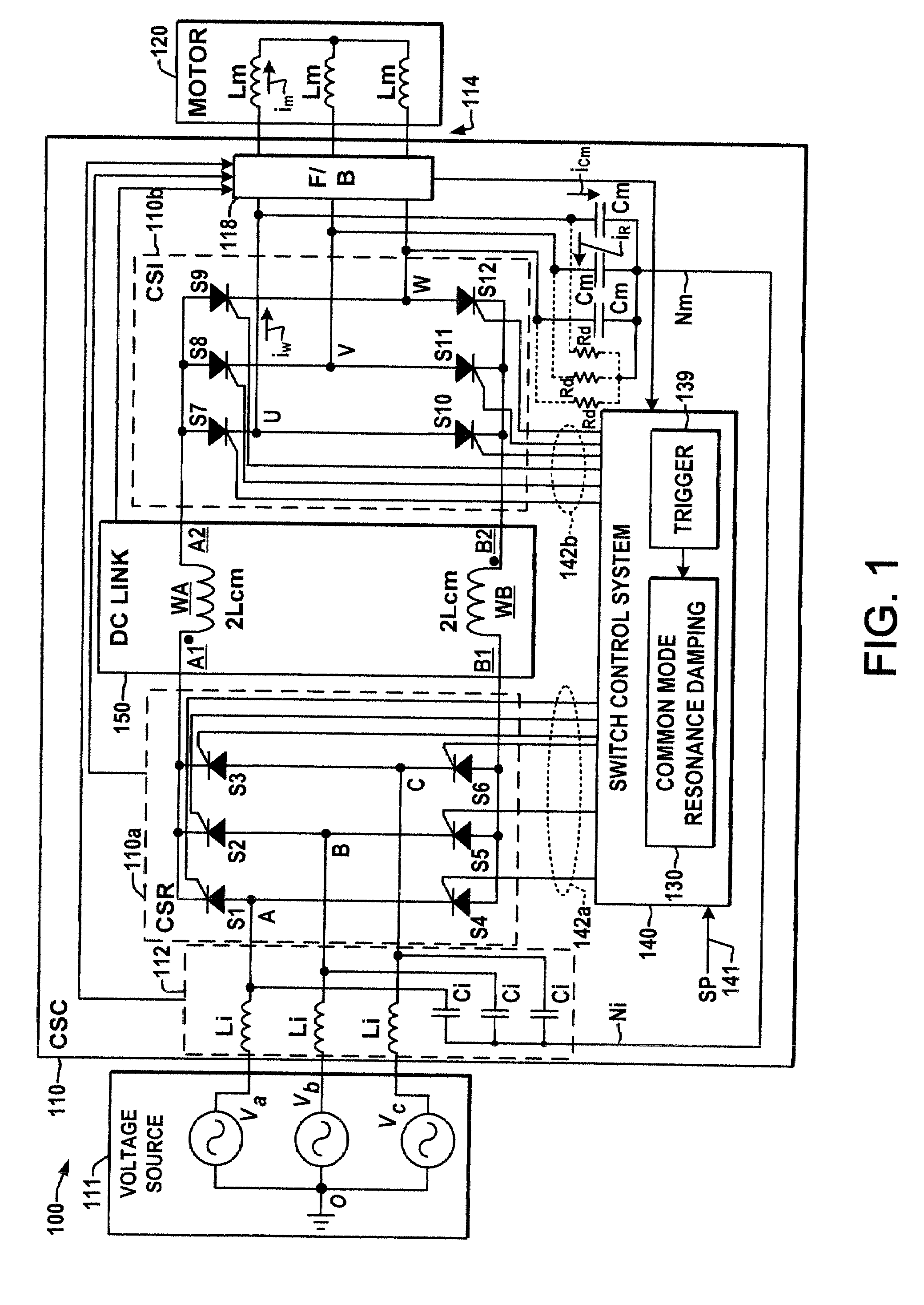
[0019]Referring now to the figures, several embodiments or implementations of the present invention are hereinafter described in conjunction with the drawings, wherein like reference numerals are used to refer to like elements throughout, and wherein the various features are not necessarily drawn to scale. FIG. 1 illustrates an exemplary system 100 including an AC voltage source 111 providing input power to a power conversion system 110 that converts the input power to drive a motor load 120 coupled to a converter output 114. The exemplary converter 110 in this example is a current source converter (CSC) 110 with an input 112 connected to the AC power source 111. While illustrated as having a three phase input 112, other embodiments may provide a single phase AC input or may include a multiphase input adapted to receive three or more input phases. The converter 110 provides variable frequency, variable amplitude multiphase AC output power at output terminals 114 for driving an AC lo...


PUM


Abstract

Power conversion systems and methods are presented for damping common mode resonance, in which inverter or rectifier switching control signals are selectively modified according to a damping resistance current value computed using a predetermined virtual damping resistance value in parallel with an output or input capacitor and a measured output or input voltage value to mitigate or reduce common mode resonance in the converter.

Description

FIELD OF THE INVENTION[0001]The present invention relates generally to electrical power conversion and more particularly to current source converter-based or voltage source converter based drive systems.BACKGROUND OF THE INVENTION[0002]Power conversion systems are used to convert input power from one form and / or level, whether AC or DC, to another (AC or DC) in a large variety of applications. One example is a pulse width modulated (PWM) current source converter used in high-power motor drives with a switching rectifier with AC input power being selectively switched to create a DC output bus voltage from which a load is driven. Power converters may include multiple stages for different types of conversion applications, such as AC / DC / AC drives for electric motors, in which input AC power of a given frequency and voltage is first converted to a DC bus, with a second stage selectively switching the DC bus power to create single or multi-phase AC output power of variable voltage and / or ...

Claims


Application Information

Patent Timeline
IPC IPC(8): H02M7/06
CPCH02M5/4585
Inventor CHENG, GEORGE ZHONGYUANZARGARI, NAVIDXIAO, YUANPANDE, MANISH
Owner ROCKWELL AUTOMATION TECH
Why Eureka
Try Eureka