
Artificial Heart

a heart and artificial heart technology, applied in the field of artificial heart, can solve the problems of unreliability, weak signals, inaccurate signals, etc., and achieve the effects of ensuring operation safety, reducing the risk of line rupture, and ensuring the minimum bending radii

Active Publication Date: 2010-04-01
PERKINELMER CELLULAR TECH GERMANY GMBH
View PDF3 Cites 15 Cited by
  • Summary
  • Abstract
  • Description
  • Claims
  • Application Information

AI Technical Summary

Benefits of technology

[0009]Because of the immediate proximity of the deriving point to the patient's heart, an ECG signal is obtained that is very detailed and allows for a precise control and regulation of the artificial heart. Besides a precise control of the blood pump or the pump drive, using the information obtained through the sensor or sensors also allows for a permanent monitoring of the patient's circulation or the patient's heart.
[0011]The signal lines connecting the electrodes with the control are located in or at the sheath of the blood line. Thus, the signal lines are quite well protected against excessive movements, bending or kinking.
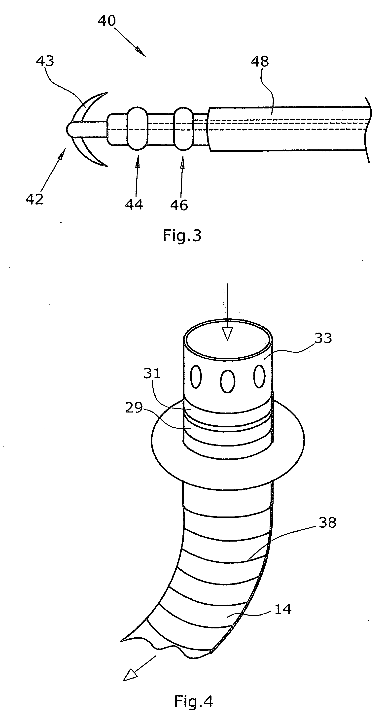
[0012]According to a preferred embodiment, the signal line or the signal lines is / are helically provided in or at the blood line sheath. Thereby the minimum bending radii of the signal lines are very large so that the risk of line ruptures is low even in the long term.
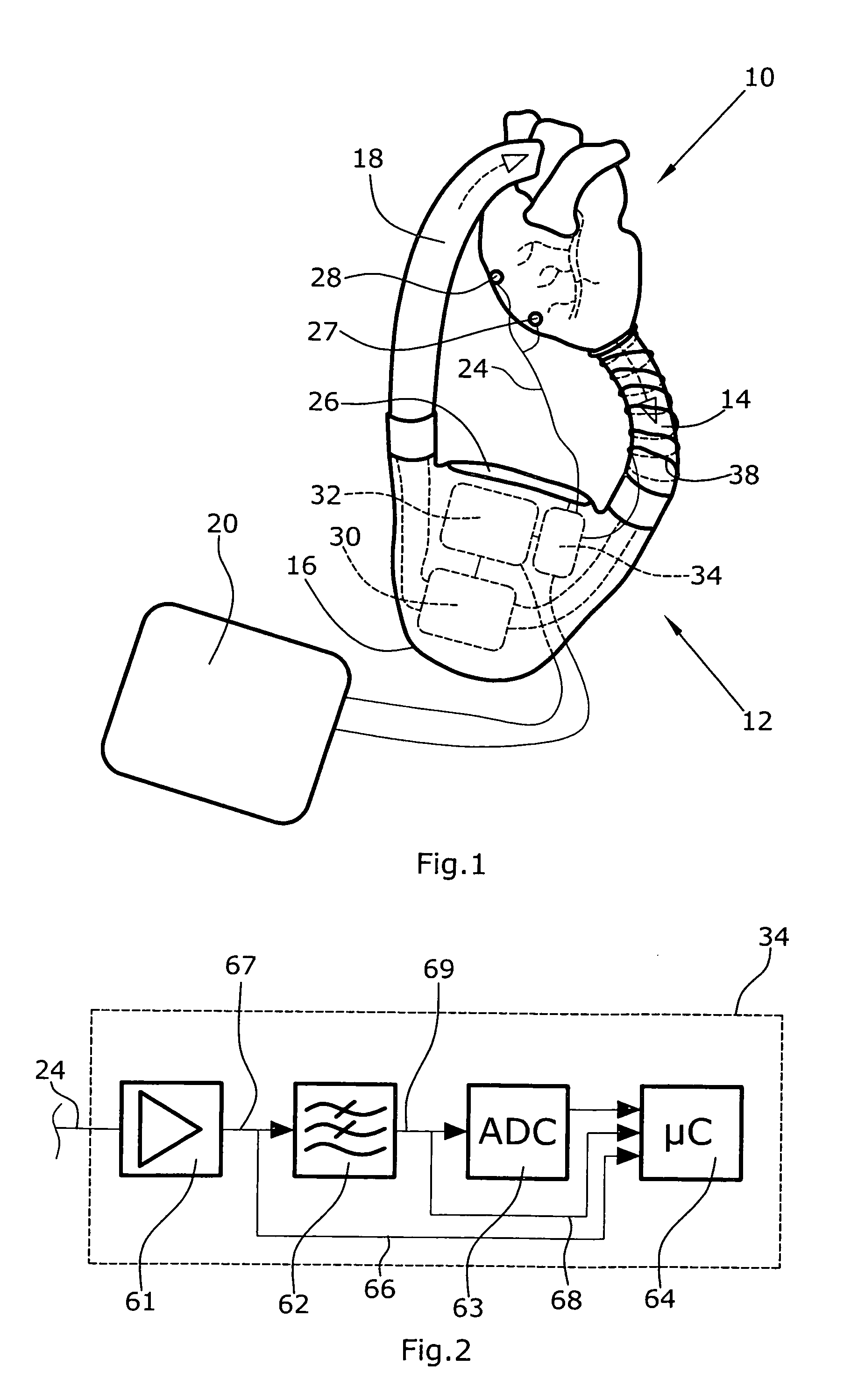
[0013]Preferably, an electric module is provided between the electrode and a control computer, at least one short-circuit line bypassing the electric module and being directly connected with the control computer. The electric module may be an amplifier and / or a filter and / or an A / D converter. When the module or the series-connected modules are operated appropriately, the electrode signal successively passes all electrode modules in order to then be supplied to the control computer in an amplified, filtered and digitalized state. Via the short-circuit line or the short-circuit lines, the same electrode signal can be supplied directly to the control computer, bypassing one, a plurality or all of the electric modules. The control computer can continuously compare the signal on the short-circuit line with a signal coming from the last electric module. Thereby, a redundancy is achieved that guarantees the operational safety that is essential to a vital implant such as an artificial heart.

Problems solved by technology

Extracorporeal artificial hearts derive ECG signals exteriorly from the skin of a patient, which signals are rather weak and inaccurate due to the distance from the heart.
These methods are limited in their accuracy and they are unreliable.

Method used


Image

  • Artificial Heart
  • Artificial Heart
  • Artificial Heart

Examples


Embodiment Construction

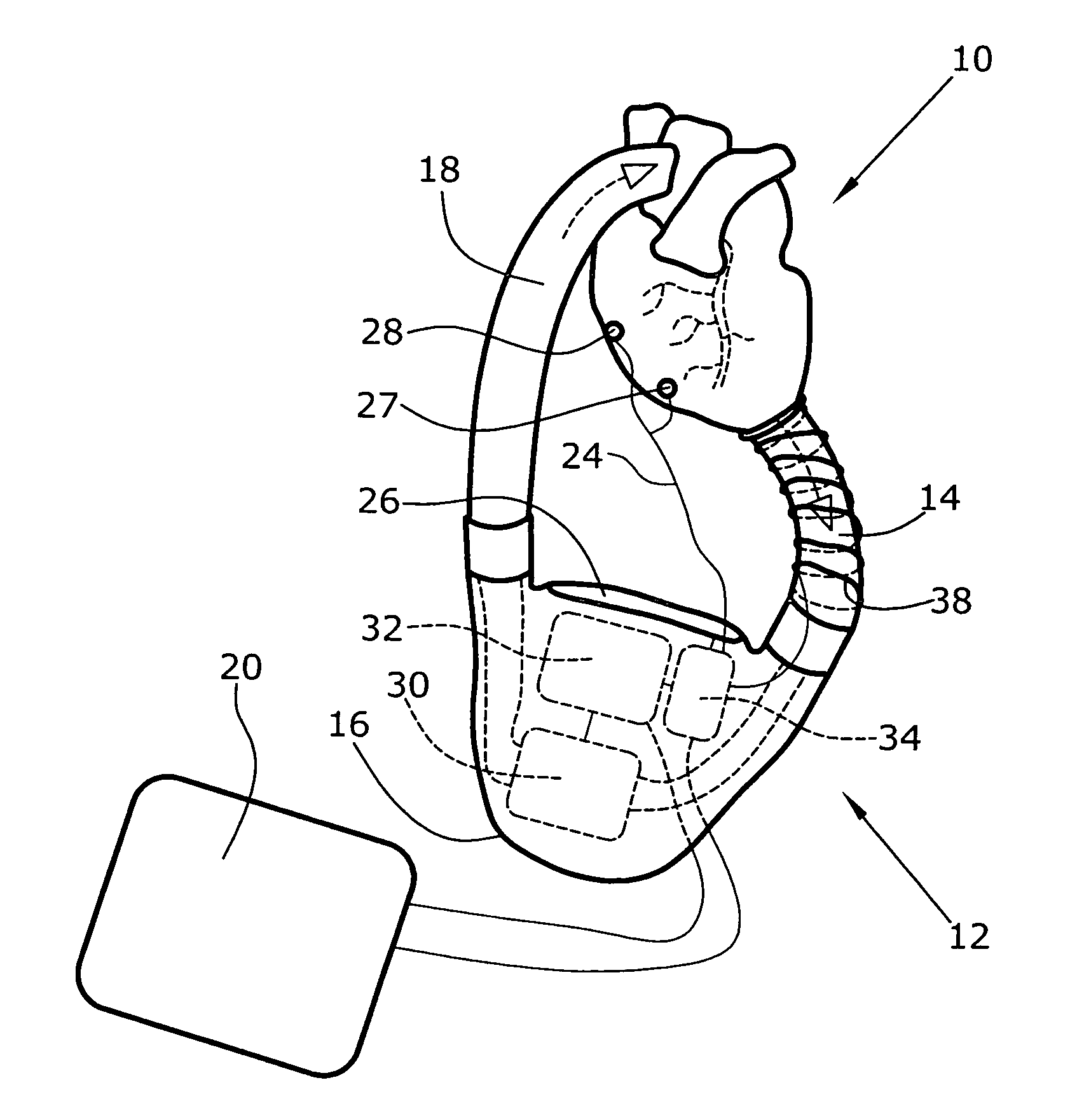
[0020]FIG. 1 illustrates a patient's heart 10 supported by an artificial heart implant 12. The artificial heart implant 12 is a so-called full implant, i.e., it has no direct physical connection to the extracorporeal.

[0021]The artificial heart implant 12 has an inlet line 14 whose inlet side is sutured to the left ventricle of the patient's heart 10, a pump unit 16 into which the inlet line 14 opens, an outlet line 18 into which blood is pumped by the pump unit 16 and which opens into the aorta of the patient's heart 10, and an intracorporeal energy supply 20 electrically connected with the pump unit 16 through signal and data lines. The inlet and outlet lines 14, 18 are blood lines.

[0022]Further, electrodes 26, 27, 28 are arranged at the pump unit 16 and connected with the pump unit 16 via corresponding signal lines 24, which electrodes are ECG electrodes serving to lead myocardially evoked signals.

[0023]The pump unit 16 comprises a mechanical blood pump 30 supporting the patient's...


PUM


Abstract

The disclosure relates to an artificial heart implant comprising a blood pump with a pump drive, a controller for controlling and regulating the pump drive, and an electrode that is connected to the controller and is used for detecting electrical quantities on the patient's heart. The controller controls the pump drive in accordance with the signals detected by the electrode.

Description

BACKGROUND[0001]1. Field of the Disclosure The disclosure refers to an artificial heart comprising a blood pump with a pump drive and a control for controlling and regulating the pump drive.[0002]2. Discussion of the Background Art[0003]In the present context, an artificial heart is to comprise all intra- and extracorporeal artificial hearts that are provided with a blood pump, i.e. extracorporeal, fully or partly implantable artificial hearts, cardiac assist systems and the like. Known artificial heart implants operate at a fixed pumping frequency or include a simple sensor system that detects and controls or regulates the motor current or the filling of the pumping chamber. Extracorporeal artificial hearts derive ECG signals exteriorly from the skin of a patient, which signals are rather weak and inaccurate due to the distance from the heart. Intracorporeal artificial hearts derive the necessary delivery rates from the motor current, the blood flow and similar parameters. These me...

Claims


Application Information

Patent Timeline
Patent Type & Authority Applications(United States)
IPC IPC(8): A61M1/12
CPCA61M1/10A61M2230/04A61M1/122A61M1/1008A61M2230/08A61M2205/33A61M2205/3303A61M60/148A61M60/40A61M60/196A61M60/538A61M60/515A61M60/20
Inventor VODERMAYER, BERNHARDSCHMID, THOMAS
Owner PERKINELMER CELLULAR TECH GERMANY GMBH
Learn More