Spark plug, and its manufacturing method

a technology of spark plugs and manufacturing methods, applied in the field of spark plugs, can solve the problems of increased possibility, increased manufacturing cost, and increased risk of ground electrode breakage, and achieve the effect of preventing the occurrence of breakage and ensuring durability

Inactive Publication Date: 2010-04-08
NGK SPARK PLUG CO LTD
View PDF13 Cites 13 Cited by
  • Summary
  • Abstract
  • Description
  • Claims
  • Application Information

AI Technical Summary

Benefits of technology

[0006]The present invention has been made to solve the above problems. It is an object of the present invention to provide a spark plug that combines good ignition performance, economy and durability.
[0009]In the spark plug of the present invention, the ground electrode has its thickness changing region formed between the large thickness region and the small thickness region in such a manner that the thickness changing region differs in position from the minimum curvature radius region of the bent shape of the ground electrode. It is therefore possible to prevent the occurrence of a breakage in the ground electrode and secure durability.

Problems solved by technology

In the case where the protruding region is formed by welding the noble metal tip to the ground electrode, the spark plug attains improved ignition performance but has a problem of increase in manufacturing cost due to the use of the expensive noble metal tip.
In the case where the protruding region of the ground electrode is formed by press forming, the press forming process causes plastic deformation in the ground electrode so that the ground electrode becomes susceptible to breakage.
This results in an increased possibility that the ground electrode will break when bent to a substantially L-shaped form during the manufacturing of the spark plug or when subjected to external force during the use of the finished plug product.
The spark plug thus has a problem of difficulty in securing durability.

Method used


Image

  • Spark plug, and its manufacturing method
  • Spark plug, and its manufacturing method
  • Spark plug, and its manufacturing method

Examples


Embodiment Construction

[0027]The present invention will be described in detail below with reference to the drawings. Herein, like parts and portions are designated by like reference numerals to avoid repeated explanations thereof.

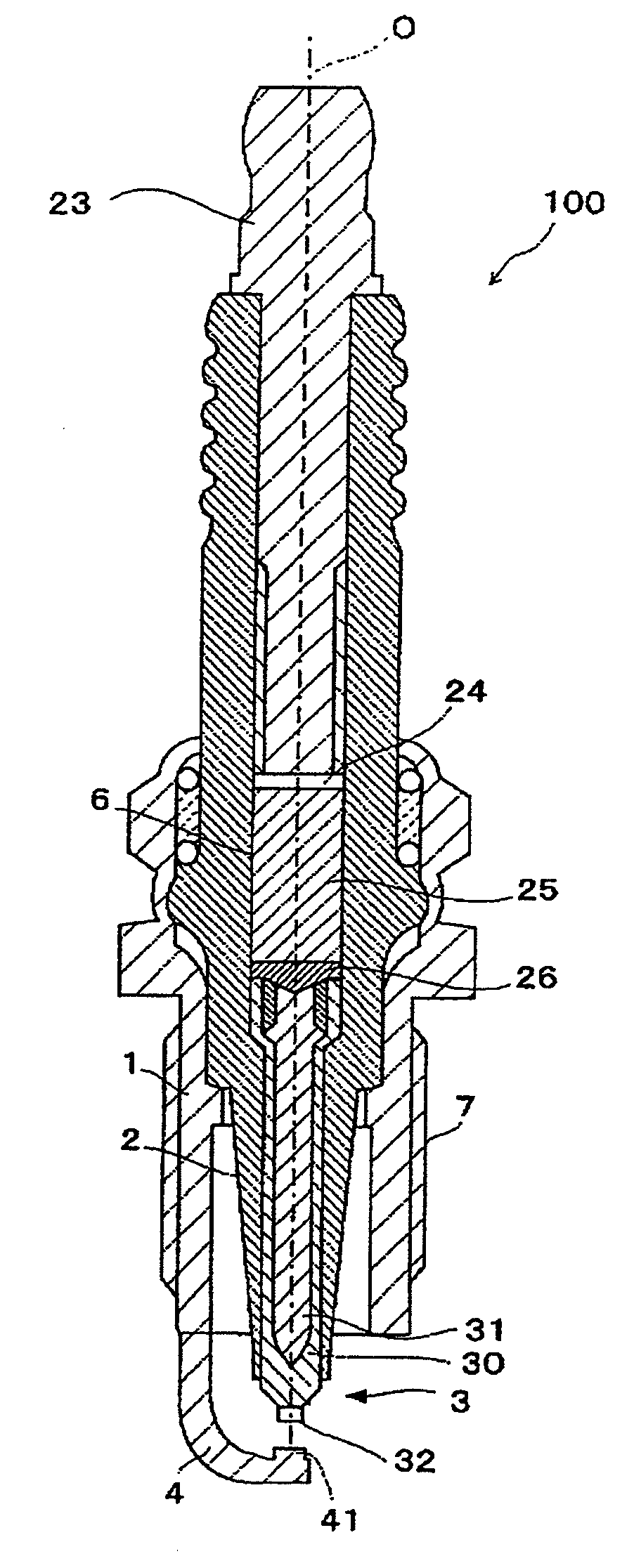
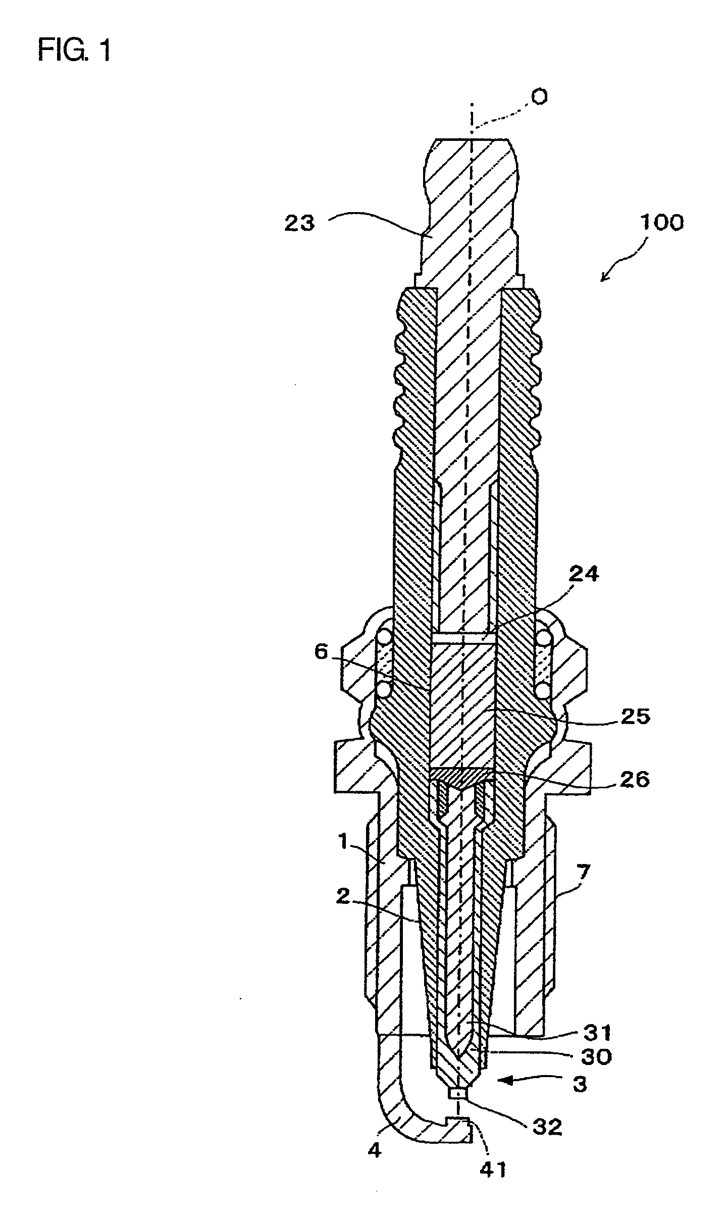
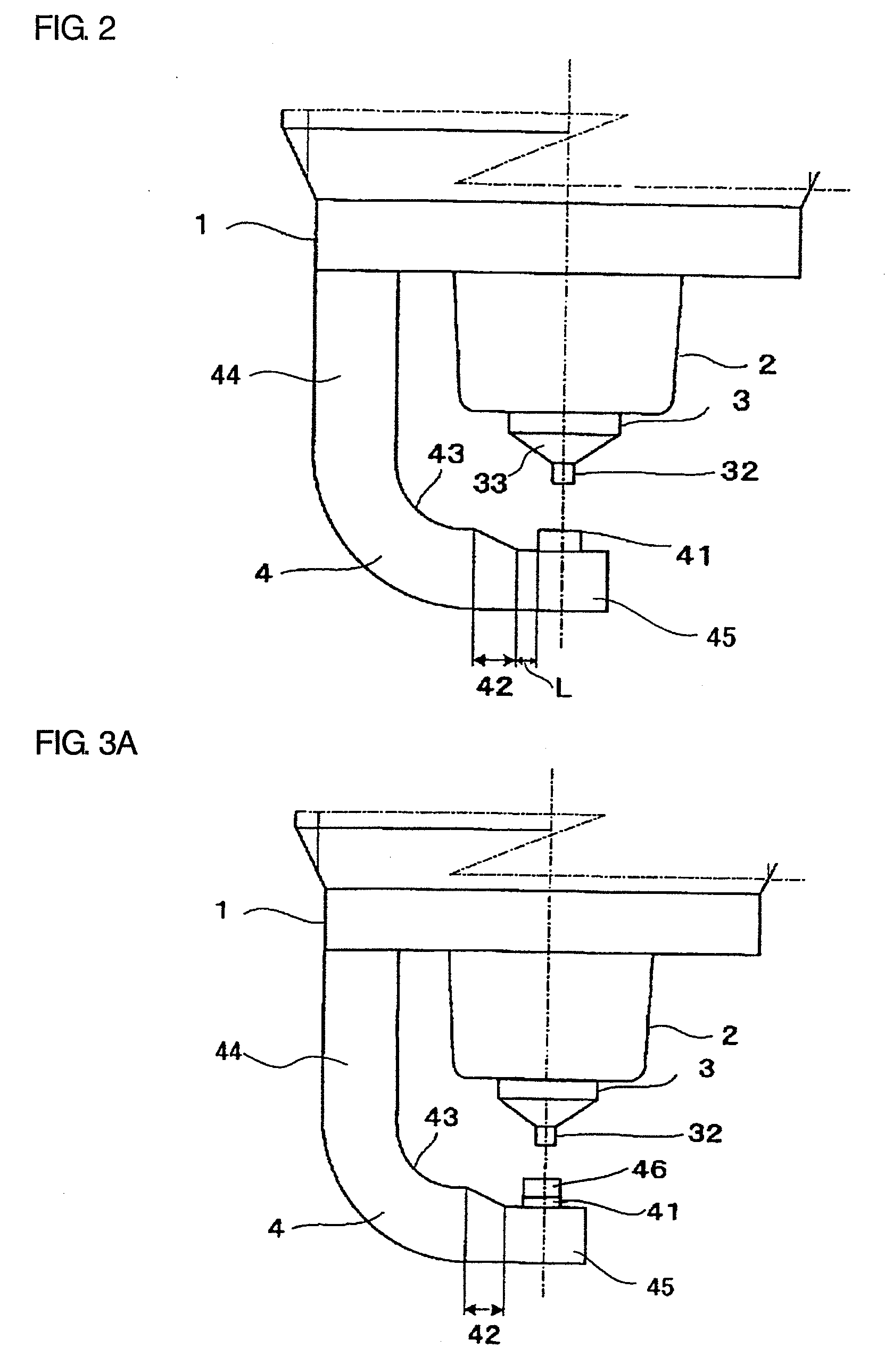
[0028]As shown in FIG. 1, a spark plug 100 according to one embodiment of the present invention includes a metal shell 1, a ceramic insulator 2, a center electrode 3 and a ground electrode 4.

[0029]The metal shell 1 is made of metal such as low carbon steel and formed into a cylindrical shape. A threaded portion 7 is formed on an outer circumferential surface of the metal shell 11 and adapted for mounting the spark plug 100 onto an engine block (not shown).

[0030]The ceramic insulator 2 is made of sintered ceramic such as alumina or aluminum nitride and retained in the metal shell 11 with a front end portion of the ceramic insulator 2 protruding from an end face of the metal shell 1.

[0031]A through hole 6 is formed through the ceramic insulator 2 in the direction of an axis O. The ...


PUM

PropertyMeasurementUnit
areaaaaaaaaaaa
thicknessaaaaaaaaaa
diameteraaaaaaaaaa

Abstract

A spark plug of the present invention includes a cylindrical metal shell, a cylindrical ceramic insulator retained in the metal shell, a center electrode retained in the ceramic insulator and extending in an axial direction, and a ground electrode formed into a bent shape and having a rear end portion fixed to the metal shell and a front end portion facing a front end portion of the center electrode with a gap left therebetween. The ground electrode contains a large thickness region formed on a rear end side thereof with a large thickness, a small thickness region formed on a front end side thereof with a smaller thickness than that of the large thickness region, a protruding region formed on the small thickness region and facing the center electrode and a thickness changing region formed between the large thickness region and the small thickness region and located at a different position from a position of a minimum curvature radius region of the bent shape of the ground electrode.

Description

TECHNICAL FIELD[0001]The present invention relates to a spark plug for use in an automotive internal combustion engine etc. and a manufacturing method thereof.BACKGROUND ART[0002]A spark plug is known which includes a center electrode and a ground electrode arranged at a discharge gap away from a front end portion of the center electrode so as to generate a spark discharge between the center electrode and the ground electrode for ignition of an air-fuel mixture in a combustion chamber of an internal combustion engine.[0003]Amid recent calls for global environmental protection, it is more strongly demanded to provide energy savings, regulate emissions of carbon dioxide and reduce emissions of unburned gases (hydrocarbon compounds). In order to satisfy these demands, developments are being actively made in internal combustion engines such as lean-burn engine, direct gasoline-injection engine and low emission gas engine. Further, exhaust gas recirculation (EGR) systems, which recircula...

Claims


Application Information

Patent Timeline
Patent Type & Authority Applications(United States)
IPC IPC(8): F23Q7/22
CPCH01T13/32Y10T29/49083H01T21/02
Inventor NAKAYAMA, KATSUTOSHINAGASAWA, SATOSHI
Owner NGK SPARK PLUG CO LTD
Why Eureka
Try Eureka