Quadrupole mass spectrometer

a mass spectrometer and quadripole technology, applied in mass spectrometers, particle separator tube details, separation processes, etc., can solve the problems of reducing the time-period for ion detection, deteriorating time resolution, and excessive waiting time-period, so as to enhance time resolution, enhance sensitivity and sn ratio, and shorten the time-period

Active Publication Date: 2010-04-08
SHIMADZU CORP
View PDF15 Cites 62 Cited by
  • Summary
  • Abstract
  • Description
  • Claims
  • Application Information

AI Technical Summary

Benefits of technology

[0025]As above, in the quadruple mass spectrometer according to each of the first to fourth aspects of the present invention, during the operation of changing between the mass values, an input voltage to be applied to the electrodes of the quadruple mass filter is quickly stabilized, so that an excessive and unnecessary waiting time-period can be shortened. Thus, for example, in the SIM or MRM measurement, even if a measurement time-period for each of the mass values is set at a constant value, a duration of a repetitive cycle for the plurality of mass values can be shortened by reducing a dead time, to enhance time resolution. In cas

Problems solved by technology

Such a voltage change inevitably involves the occurrence of a certain level of overshoot (or undershoot) and ringing.
Thus, as the settling time-period becomes longer, a time interval between measurements for the same mass value in adjacent cycles becomes larger, to cause deterioration in time resolution.
Although a duration of one cycle may be shortened to enhance the time resolution, it causes a reduction in ion detection time-period for each of the mass values, which leads to deterioration in sensitivity and SN ratio.
In the case where the mass values are randomly set as shown in FIG. 9B, an amount of voltage change becomes larger on average, and thereby the settling time-period undesirably becomes longer.
Further, if the quadrupole mass filter is set to allow a large number of ions to pass therethrough during a transitional peri

Method used


Image

  • Quadrupole mass spectrometer
  • Quadrupole mass spectrometer
  • Quadrupole mass spectrometer

Examples


Embodiment Construction

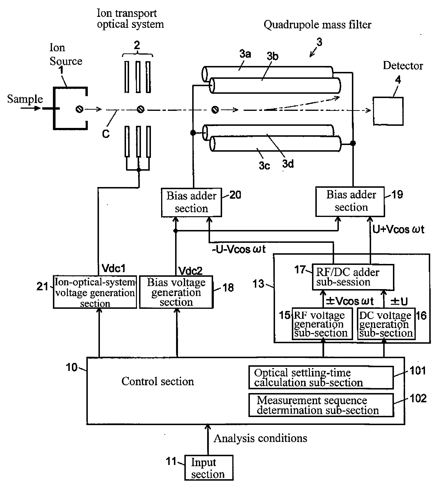
[0036]With reference to the accompanying drawings, the present invention will now be described based on one exemplary embodiment thereof. FIG. 1 is a fragmentary block diagram showing a quadruple mass spectrometer according to this embodiment.

[0037]The quadruple mass spectrometer according to this exemplary embodiment comprises an ion source 1, an ion transport optical system 2, a quadrupole mass filter 3 and an ion detector 4, which are installed inside a vacuum chamber (not shown). The quadrupole mass filter 3 includes four rod electrodes 3a, 3b, 3c, 3d each disposed to be inscribed in a circular cylindrical plane having an axis defined by an ion optical axis C and a given radius with a center on the axis. The four rod electrodes 3a, 3b, 3c, 3d are arranged to form two pairs each disposed in opposed relation across the ion optical axis C (i.e., the pair of rod electrodes 3a, 3c and the pair of rod electrodes 3b, 3d), and each of the pair of rod electrodes 3a, 3c and the pair of ro...


PUM


Abstract

Disclosed is a quadrupole mass spectrometer, which is capable of, during an SIM measurement, maximally reducing a settling time-period necessary for an operation of changing an input voltage to a quadrupole mass filter in a staircase pattern, and preventing unwanted ions from excessively entering a detector during a course of changing between a plurality of mass values. Under a condition that a response speed of a DC voltage U to be applied to quadrupole electrodes is less than that of an amplitude of a high-frequency voltage V, a control section 10 is operable to rearrange the mass values in descending order of mass value, and an optimal settling-time calculation sub-section 101 is operable to determine a settling time-period for each of the mass values, based on a mass-value difference and a post-change mass value.

Description

BACKGROUND OF THE INVENTION[0001]1. Field of the Invention[0002]The present invention relates to a quadrupole mass spectrometer using a quadrupole mass filter as a mass analyzer operable to separate ions according to mass values (e.g., m / z (mass-to-charge ratio) values).[0003]2. Description of the Background Art[0004]A quadrupole mass spectrometer is designed to apply a voltage (input voltage) formed by superimposing a high-frequency (e.g., radio-frequency) voltage on a direct-current (DC) voltage, to four rod electrodes constituting a quadrupole mass filter, to allow only an ion having a mass corresponding to a value of the input voltage to selectively pass through the quadrupole mass filter and reach an ion detector. Recently, a gas chromatograph / mass spectrometer (GC / MS) and a liquid chromatograph / mass spectrometer (LC / MS) produced by combining the quadrupole mass spectrometer with respective ones of a gas chromatograph and a liquid chromatograph are widely used in various fields...

Claims


Application Information

Patent Timeline
IPC IPC(8): H01J49/04H01J49/42
CPCH01J49/0077
Inventor KAWANA, SHUICHI
Owner SHIMADZU CORP
Why Eureka
Try Eureka