Sealing device and production method thereof

a sealing device and sealing technology, applied in the direction of brake systems, manufacturing tools, machines/engines, etc., can solve the problems of reducing sealing performance, low sealing performance, damage or breakage, etc., to improve the sliding property of the sealing ring, reduce the cost of materials, and reduce sliding resistance

Inactive Publication Date: 2010-04-08
NOK CORP
View PDF2 Cites 16 Cited by
  • Summary
  • Abstract
  • Description
  • Claims
  • Application Information

AI Technical Summary

Benefits of technology

[0028]As described in the foregoing, according to the present invention, it is possible to achieve a reduction in the sliding resistance. In addition, a general-purpose resin can be used for a high pressure piston seal comprising four members because of the improvement in the sliding property of the seal ring, and hence the cost of materials can be reduced, thus making it possible to produce the piston seal at low cost. Further, in a sealing device comprising two members of a seal ring made of a resin and an elastic ring, if PTFE is applied which is used generally and widely as a sliding material, the sliding property of the sealing device can be further improved, and if a general-purpose resin is applied, the cost of materials can be reduced, so a low cost production of the sealing device becomes possible. In other words, the present application is not limited to such combined sealing devices, but can achieve the reduction of the sliding resistance with respect to resin-made sliding members (for example, seal rings, wear rings, etc.) in a simple manner.
[0029]More specifically, the present invention is able to achieve, in a sealing device provided with a sliding surface, an improvement in the sliding property of the sealing device by devising the shape of the sliding surface without regard to the characteristic or property of materials used. Accordingly, the range of selection of materials can be extended (i.e., it becomes possible to adopt inexpensive materials having not so high sliding properties), whereby the reduction in the cost of materials can be made. In addition, it can be made possible to satisfy a request for an excellent sliding property with the use of a single member, although in the past, a plurality of kinds of members are combined so as to achieve an improvement in the sliding property while supplementing their individual properties with each other. Accordingly, a reduction in the cost of materials can be made due to a reduction in the number of component members required.

Problems solved by technology

Although this sealing device is intended to reduce sliding resistance by the use of PTFE for the seal ring which slides with respect to a counterpart member, it is inferior, in pressure resisting ability against hydraulic pressure, to those made of nylon (polyamide type resin), so it would sometimes be damaged or broken upon application of high pressure while giving rise to a phenomenon of protrusion.
In addition, a spiral groove formed on a sliding surface of the seal ring acts to place a pressure side and a non-pressure side in communication with each other to form an oil leakage passage, as a result of which there is a problem of low sealing performance.
However, there is the following problem.
That is, even if a flaw or the like is generated in each annular protrusion at one place thereof, lubrication grooves between adjacent ones of the individual annular protrusions are placed in communication with each other, so that a leakage passage leading from a pressure side up to a non-pressure side is liable to be formed, thus easily reducing the sealing performance.
In another words, it can be said that a safety factor with respect to the sealing performance is low.
Moreover, in a patent document 3, there is proposed a sealing device which is intended to improve the lubrication property by providing a plurality of holes which serve to connect between an inner peripheral surface and an outer peripheral surface of a low friction ring, but there is a problem that the strength of the low friction ring itself is decreased due to the provision of the holes.
In addition, there is also another problem that upon application of high pressure, an elastic seal ring (a back ring made of rubber) is caused to protrude into the holes in the inner peripheral surface of the low friction ring, thus resulting in its damage.
However, when flaws or the like are generated in a pair of annular protrusions, respectively, which form opposite side walls of the oil groove 700, a leakage passage for the fluid to be sealed might be formed, thereby giving rise to a fear that the sealing performance of the seal ring 200 might be easily decreased.
In addition, in order for the oil groove 700 to exhibit the function of the pressure chamber to a satisfactory extent, a prescribed sliding distance is required, and hence there is a possibility that an expected effect might not be achieved in an initial stage of operation.
However, there is the following problem.
In addition, in case where nylon is used as a material for the piston seal, the pressure resisting ability is more excellent but the sliding resistance be comes higher, in comparison with the case of using PTFE, so there is a problem that when a hydraulic cylinder is operated, a so-called stick-slip phenomenon will occur, thus ma king it easy to generate vibration.
However, this sealing device is composed of the four members, and hence has a problem in that it is poor from a cost point of view.

Method used


Image

  • Sealing device and production method thereof
  • Sealing device and production method thereof
  • Sealing device and production method thereof

Examples


first embodiment

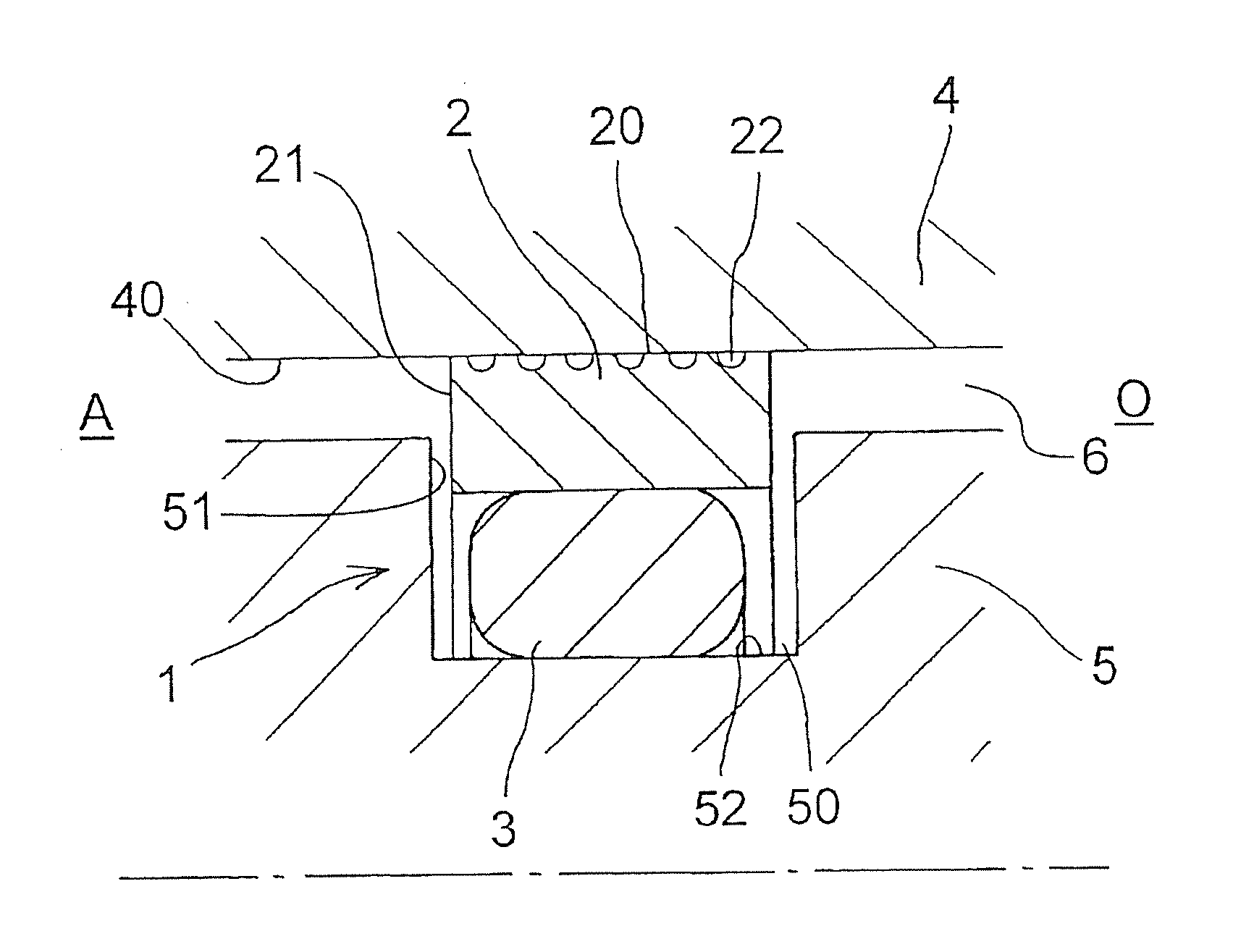
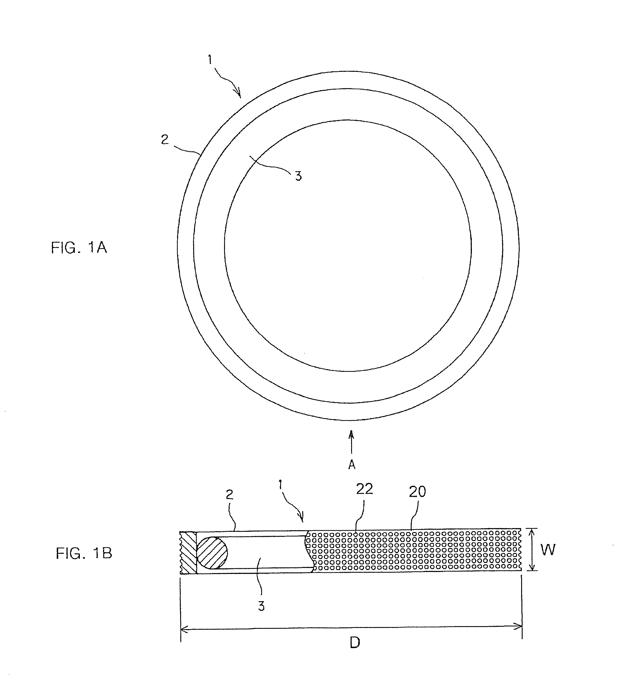
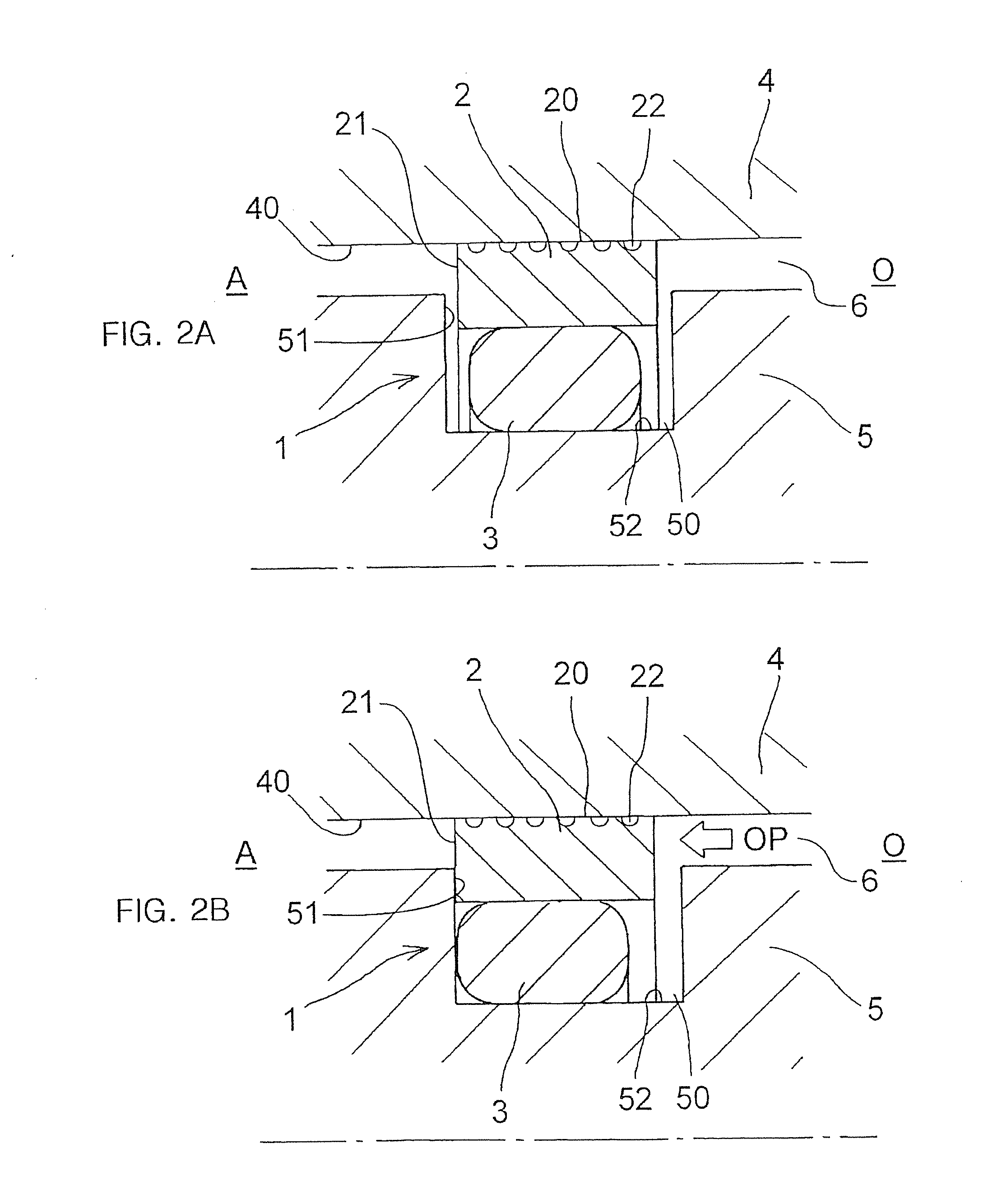
[0059]A sealing device according to a first embodiment of the present invention will be described while referring to FIG. 1 and FIG. 2. FIG. 1 is a schematic diagram showing the construction of the sealing device according to this embodiment, wherein FIG. 1A shows an appearance thereof as seen in an axial direction, and FIG. 1B is an arrow view as seen from arrow A of FIG. 1A, showing a partial cross section thereof. FIG. 2 is a schematic half cross sectional view showing a mounted state of the sealing device according to this embodiment, wherein FIG. 2A shows a state with no pressure applied, and FIG. 2B shows a state with pressure applied.

[0060]The sealing device 1 according to this embodiment is used, for example, as a sealing device for a piston in a hydraulic cylinder, i.e., a so-called piston seal that is fitted into an annular groove formed on an outer peripheral surface of the piston for sealing an annular clearance or gap between the piston and the cylinder.

[0061]The sealin...

second embodiment

[0087]A sealing device according to a second embodiment of the present invention will be described while referring to FIG. 5. FIG. 5 is a schematic cross sectional view showing the sealing device 1′ according to the second embodiment. Here, note that constructions common to those of the first embodiment are identified by the same symbols and an explanation thereof is omitted. Constructions, their operational effects and the like not particularly described are similar to those in the first embodiment.

[0088]The outer peripheral surface 20 of the seal ring 2 has axially opposite sides thereof formed into taper surfaces 24, respectively. With this, the sliding area with respect to the inner peripheral surface 40 of the housing 4 becomes small, and the sliding resistance thereof can be reduced. In addition, the contact pressure of the outer peripheral surface 20 with respect to the inner peripheral surface 40 of the housing 4 can be reduced by a wedge effect that is produced by the fluid...


PUM

PropertyMeasurementUnit
depthaaaaaaaaaa
depthaaaaaaaaaa
outer diameteraaaaaaaaaa

Abstract

A sealing device is provided which is capable of reducing its sliding resistance. In a sealing device 1 which is fitted into an annular groove formed in one of a housing with a shaft hole and a shaft inserted into said shaft hole and serves to seal an annular gap between these two members, and which includes a seal ring 2 made of a resin that is in sliding contact with the other of the two members, and an elastic ring 3 that is fitted between the seal ring 2 and the annular groove, the seal ring has a plurality of concave portions 22 formed on its sliding surface 20 which is in sliding contact with the other member.

Description

TECHNICAL FIELD[0001]The present invention relates to a sealing device used for a hydraulic cylinder or the like as well as to a production method of the sealing device.BACKGROUND ART[0002]In sealing devices used for hydraulic cylinders that are adapted to be used as driving means for construction machinery, there have been proposed a variety of types of sealing devices in order to improve the lubrication property of sliding surfaces (see under-mentioned individual patent documents).[0003]For example, in a patent document 1, a sealing device is proposed which is constructed of a seal ring made of PTFE (polytetrafluoroethylene resin) and a thrust ring made of a rubbery elastic material is proposed. Although this sealing device is intended to reduce sliding resistance by the use of PTFE for the seal ring which slides with respect to a counterpart member, it is inferior, in pressure resisting ability against hydraulic pressure, to those made of nylon (polyamide type resin), so it would...

Claims


Application Information

Patent Timeline
Patent Type & Authority Applications(United States)
IPC IPC(8): F16J15/16B23K26/00F16J15/18F16J15/3284
CPCF15B15/1452F16J15/3208F15B15/1461F15B15/14F16J15/18
Inventor MAEDA, TOSHIYUKIABE, YOSHIYUKI
Owner NOK CORP
Why Eureka
Try Eureka