Control device for induction motor

Inactive Publication Date: 2010-04-08
YASKAWA DENKI KK
View PDF6 Cites 9 Cited by
  • Summary
  • Abstract
  • Description
  • Claims
  • Application Information

AI Technical Summary

Benefits of technology

[0010]A control device according to a first aspect of the present invention includes a pulse width modulation (PWM) inverter unit that drives an induction motor by outputting command voltage, a current detector that detects motor current that passes through the induction motor, a voltage error observer unit that estimates a command voltage error using the command voltage and the motor current, a voltage error correction unit that corrects the command voltage using the command voltage error, and a slip correction unit that calculates a slip correction amount using the command voltage error and

Problems solved by technology

Thus, the slip frequency can

Method used


Image

  • Control device for induction motor
  • Control device for induction motor
  • Control device for induction motor

Examples


first embodiment

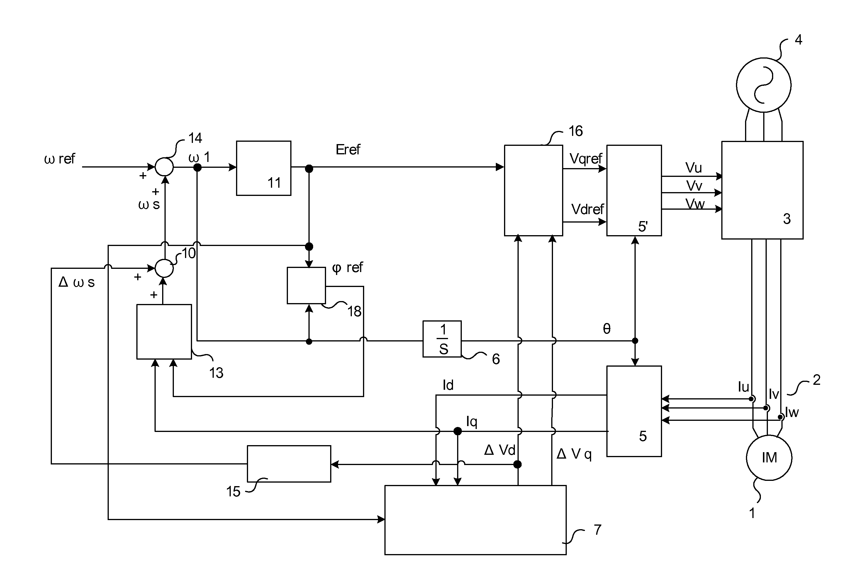
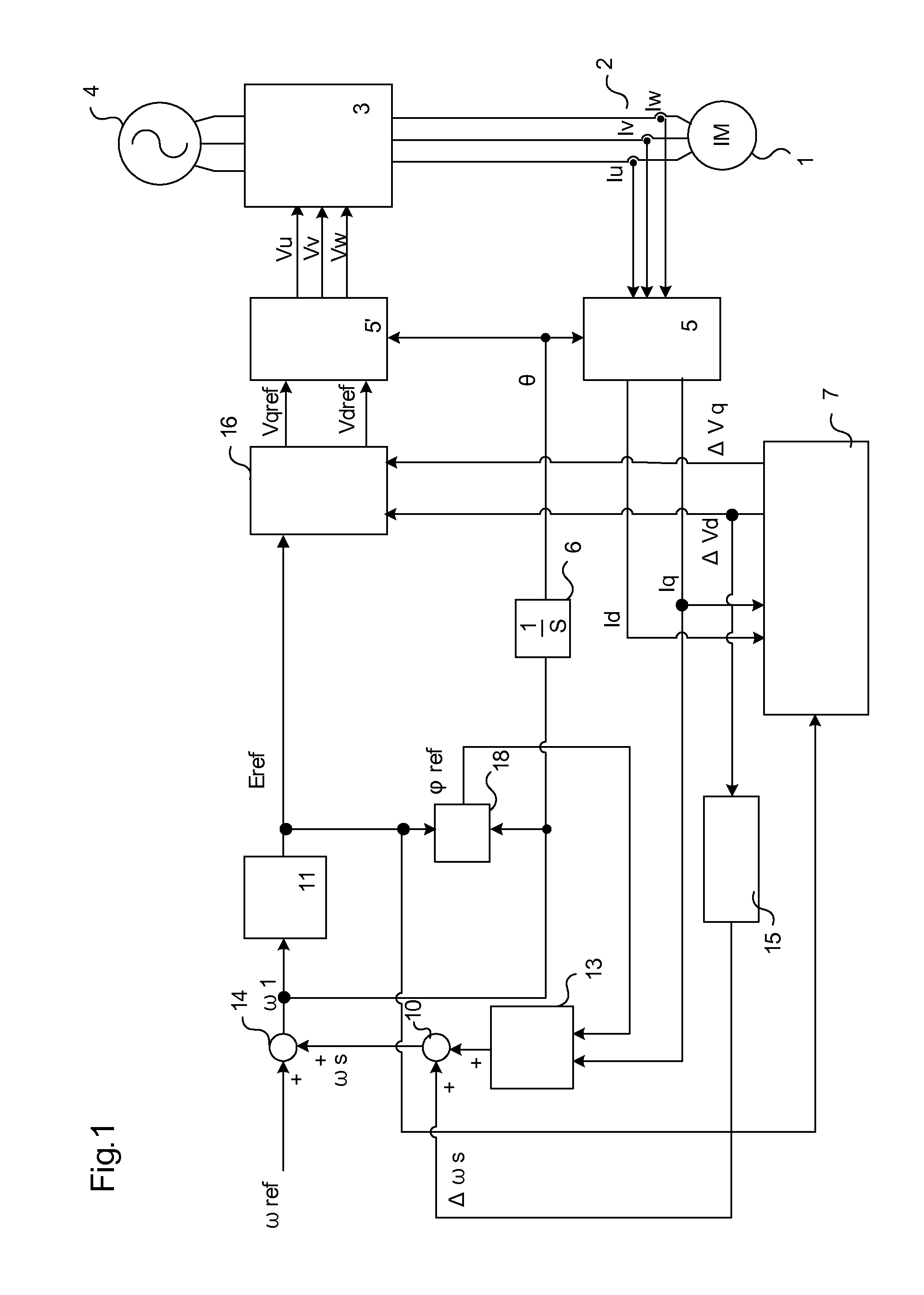
[0027]FIG. 1 is a block diagram of a control device I according to the present invention for an induction motor.

[0028]The control device I includes a current detector 2 that detects phase currents Iu, Iv, and Iw of motor currents that pass through a motor 1 and a pulse width modulation (PWM) inverter 3 the power supply of which is a three-phase alternating current power supply 4.

[0029]The control device I further includes a coordinate transformation unit 5 that transforms the phase currents Iu, Iv, and Iw into a d-axis current Id and a q-axis current Iq of a rotating coordinate system, using an electrical angle θ described below, and a coordinate transformation unit 5′ that transforms the command voltage Vref=[Vdref Vqref]T (Vdref: d-axis command voltage, Vqref: q-axis command voltage) described below into three-phase command voltages Vu, Vv, and Vw of a stationary reference frame, using the electrical angle θ.

[0030]The control device I further includes an integrator 6 that calculat...

second embodiment

[0055]FIG. 3 is a block diagram showing the components of a control device according to the present invention for an induction motor. FIG. 3 is different from FIG. 1 in that current control units 8A and 8B, an F / F command voltage calculation unit 9, and peripheral circuits are additionally provided, and a d-axis command current calculation unit 17 calculates the magnetic flux command φref. The peripheral circuits are a q-axis command current calculation unit 12, subtracters 19 and 20, and adders 21, 22, and 23. Moreover, the reference numeral of the voltage error correction unit is changed from 16 to 16′, and there are differences in some operations. The same reference numerals as in FIG. 1 are assigned to corresponding components that operate in the same manners as in FIG. 1, and the description is omitted here.

[0056]The second embodiment will now be described, focusing on the differences between the first embodiment and the second embodiment.

[0057]The d-axis command current calcul...


PUM


Abstract

A control device includes a slip calculator that calculates a first slip frequency of an induction motor, a current detector that detects motor current that passes through the induction motor, an adder that calculates a primary frequency by adding a speed command and a second slip frequency that are given, a command voltage generation unit that generates first command voltage from the primary frequency, a voltage error observer unit that estimates a command voltage error from the first command voltage and the motor current, a slip correction unit that calculates a slip correction amount from the command voltage error, an adder that calculates the second slip frequency by adding the first slip frequency and the slip correction amount, and a voltage error correction unit that corrects the first command voltage using the command voltage error and outputs second command voltage.

Description

CROSS-REFERENCES TO RELATED APPLICATION[0001]The present application is related to Japanese Patent application no. 2008-257015 filed at Japan Patent Office titled “Induction Motor Controller and Its Control Method”, all of which are incorporated herein by reference.BACKGROUND OF THE INVENTION[0002]1. Field of the Invention[0003]The present invention relates to a control device that controls an induction motor without using a speed sensor and a control method of the control device.[0004]2. Description of Related Art[0005]In general slip frequency type speed-sensorless control, a primary frequency is calculated by adding a slip frequency to estimated motor speed, and a magnetic flux phase is calculated by integrating the primary frequency. The slip frequency is calculated on the basis of set secondary resistance. A value measured using an auto-tuning method, a value obtained by a combined test, or a motor design value is used as the value of the secondary resistance.[0006]When a motor...

Claims


Application Information

Patent Timeline
IPC IPC(8): H02P23/08H02P21/00H02P21/13H02P27/04H02P21/14H02P21/18H02P21/24H02P23/07H02P23/12H02P23/14
CPCH02P21/085H02P21/09
Inventor SATO, SADAYUKIIURA, HIDEAKIYAMAMOTO, YOICHIIDE, KOZO
Owner YASKAWA DENKI KK
Why Eureka
Try Eureka