Battery pack for power tool, and power tool

a battery pack and power tool technology, applied in the field of battery pack for power tools and power tools, can solve the problems of reducing the remaining battery capacity to zero, affecting the accuracy of monitoring, and always consuming the electric power of the battery by the monitoring circuit, so as to reduce the electric power consumption of the battery, inhibit the overdischarge of the battery, and accurately monitor the

Inactive Publication Date: 2010-04-08
MAKITA CORP
View PDF17 Cites 59 Cited by
  • Summary
  • Abstract
  • Description
  • Claims
  • Application Information

AI Technical Summary

Benefits of technology

[0041]As just described, if the battery pack is returned from the sleep mode to the normal operational state when the battery voltage falls below the lower limit of the voltage threshold range, the shutdown mode switching unit switches the battery pack to the shutdown mode, thereby further reducing the electric power consumption of the battery and inhibiting overdischarge of the battery.
[0042]The battery pack may include a charge detecting unit that detects that a battery charger for charging the battery is connected to the battery pack. When the charge detecting unit detects that the battery charger is connected, the mode returning unit may perform processing to return the battery pack from the sleep mode to the normal operational state as a processing to be performed when the mode returning condition is met. Due to this, the battery pack is returned to the normal operational state when the battery charger is connected thereto, and the monitoring circuit is made to monitor the battery pack as per normal, whereby the battery during the charge can be accurately monitored.
[0043]By configuring the above battery pack of the present invention to be detachably attached to a tool body operated by receiving power supply from the battery pack, a power tool can be composed of the tool body and the battery pack. According to the power tool configured as such, the electric power consumption of the battery inside the battery pack is effectively reduced and, therefore, charging of the battery pack can be decreased in frequency, which enables providing a user-friendly power tool.

Problems solved by technology

When the monitoring circuit, which is always in operation, is provided in the battery pack as above, it is inevitable that electric power of the battery is always consumed by the monitoring circuit although in a small amount.
Consequently, even if the battery is not supplying electric power to the power tool, a remaining battery capacity gradually decreases to zero in a comparatively short period of time.
Due to properties of the battery, however, the decreased battery voltage and the increased battery temperature as a result of the discharge do not recover immediately after the discharge is finished, but require a certain period of time to return to an original state.
And while the battery is in such an unstable state, an abnormality may occur in the battery due to a certain cause.
However, even such a momentary short circuit remains an abnormality which has occurred inside the battery cell.
Therefore, it is necessary to provide a process which can detect the occurrence of the slight short circuit and make the battery unusable after the detection.
However, if the operation of the monitoring circuit is stopped by switching the battery pack to the sleep mode immediately after the discharge is finished in order to reduce electric power consumption of the battery, the abnormality such as the above slight short circuit cannot be detected.
That is because the monitoring circuit is not in operation for some period of time after the discharge is finished, when the unstable state continues in which the abnormality such as the slight short circuit is highly likely to occur as described above.
However, it is extremely difficult to accurately determine the time period required until the battery goes into a stable state after the discharge because such a time period is greatly influenced by the current and temperature during the discharge, a level of deterioration of the battery cell, and the like.
Consequently, the time period cannot help but be set comparatively long, so that the monitoring circuit is steadily in operation until the battery goes into a stable state, even in a case where it takes the longest time for the battery to go into a stable state.
Therefore, it is difficult to effectively reduce the electric power consumption of the battery.

Method used


Image

  • Battery pack for power tool, and power tool
  • Battery pack for power tool, and power tool
  • Battery pack for power tool, and power tool

Examples


Embodiment Construction

(1) General Structure of Rechargeable Impact Driver

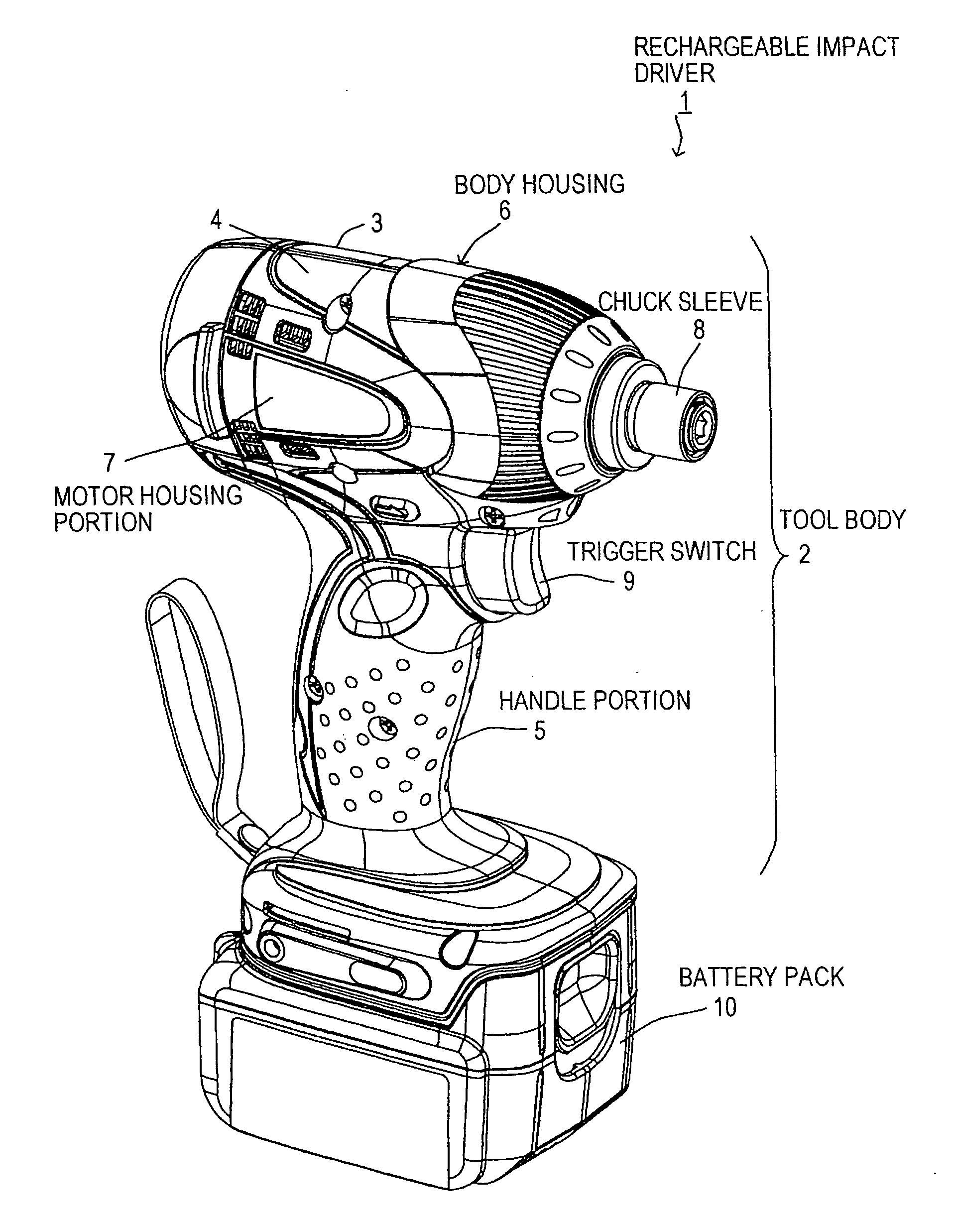
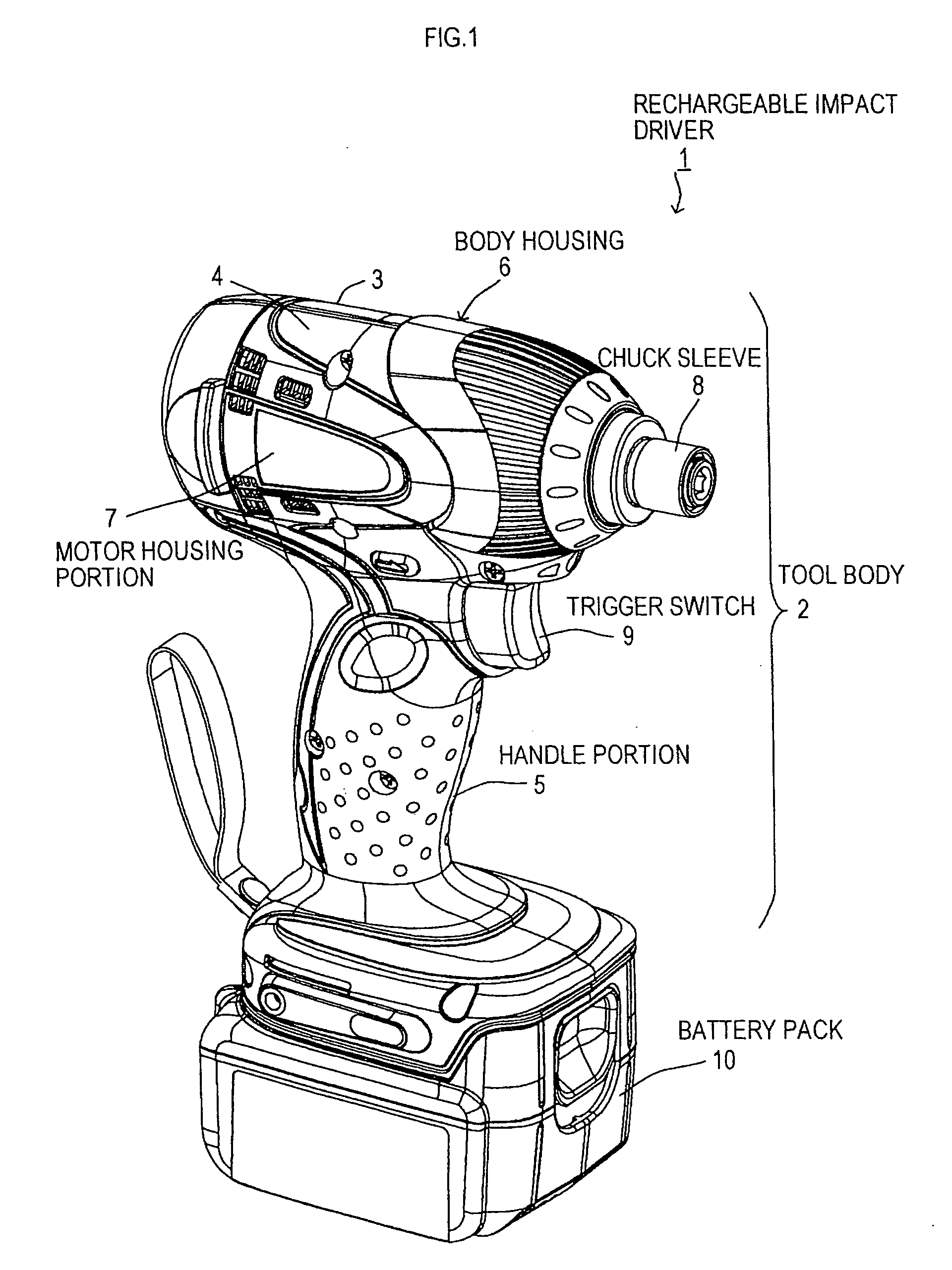
[0050]As shown in FIG. 1, a rechargeable impact driver 1 in the present embodiment includes a tool body 2 and a battery pack 10. The battery pack 10 is detachably attached to a lower end of the tool body 2. The tool body 2 is formed by assembling right and left half housings 3 and 4. The tool body 2 includes a body housing 6 with a handle portion 5 provided in an extending manner in a lower part thereof. The battery pack 10 is detachably attached to a lower end of the handle portion 5 of the body housing 6.

[0051]A motor housing portion 7 for housing a motor 65 (a direct current motor in the present embodiment as shown in FIG. 3) as a power source of the rechargeable impact driver 1 is provided at a rear (on a left side in FIG. 1) of the body housing 6. A decelerating mechanism and a percussion mechanism are housed ahead of the motor housing portion 7. A chuck sleeve 8 for attaching a tool bit (not shown) to a top end of the percussi...


PUM

PropertyMeasurementUnit
voltageaaaaaaaaaa
voltageaaaaaaaaaa
total voltageaaaaaaaaaa

Abstract

A battery pack for power tool includes a battery, a monitoring circuit, and a sleep mode switching unit. The battery includes at least one battery cell. The monitoring circuit is operated by receiving power supply from the battery. The sleep mode switching unit switches the battery pack to a sleep mode by stopping at least a part or all of operations of the monitoring circuit when the monitoring circuit detects a discharge end state where a discharge current from the battery is equal to or lower than a predetermined set current value, and the monitoring circuit further detects at least one of a voltage stable state where a voltage change amount in the battery cell is within a predetermined stable range of voltage change amount and a temperature stable state where a temperature change amount in the battery is within a predetermined stable range of temperature change amount.

Description

CROSS-REFERENCE TO RELATED APPLICATIONS[0001]This application claims the benefit of Japanese Patent Applications No. 2008-261825 filed Oct. 8, 2008, No. 2008.287765 filed Nov. 10, 2008, No. 2009-002596 filed Jan. 8, 2009, and No. 2009-007664 filed Jan. 16, 2009 in the Japan Patent Office, the disclosure of which are incorporated herein by reference.BACKGROUND[0002]The present invention relates to a battery pack for power tool which includes a rechargeable battery which is repeatedly rechargeable, and a power tool to which the battery pack for power tool is attached and which is operated by receiving power supply from the battery pack for power tool.[0003]In a battery pack for power tool using a battery which includes a lithium-ion rechargeable battery (hereinafter also referred to as “a battery pack”), there is generally provided a monitoring circuit. The monitoring circuit is operated using the battery as a power source. The monitoring circuit is provided because it is necessary to...

Claims


Application Information

Patent Timeline
Patent Type & Authority Applications(United States)
IPC IPC(8): H02J7/04H02J7/00H01M50/503H01M50/543
CPCB25F5/00H01M2/30H01M10/4207H02J2007/0098H01M10/482H01M10/486H02J7/0063H01M10/4257Y02E60/10H01M50/543H02J7/007182H02J7/007194
Inventor SUZUKI, HITOSHIKOBAYAKAWA, TADAHIKOMURAMATSU, TOMOO
Owner MAKITA CORP
Why Eureka
Try Eureka