Illuminating Device For Tools

a technology of illumination device and tool, which is applied in the direction of semiconductor devices for light sources, lighting and heating apparatus, lighting applications, etc., can solve the problems of short life of conventional halogen light bulbs, inconvenient use, and excessive electrical power consumption of bulbs, so as to reduce radiation heat, reduce the cost of electricity, and prevent the effect of radiation heat from affecting the precision of objects being processed

Inactive Publication Date: 2010-04-08
AVEX SG TECH +2
View PDF6 Cites 17 Cited by
  • Summary
  • Abstract
  • Description
  • Claims
  • Application Information

AI Technical Summary

Benefits of technology

[0017]A fifth objective of the invention is to provide an illuminating device for tools that has a lower radiation heat because it is a cold light source. This can effectively prevent the radiation heat from affecting the precision of object being processed.
[0018]A sixth objective of the invention is to provide an illuminating device for tools that effectively confines light beams from the LED lamp to avoid halos.
[0019]To achieve the above-mentioned objectives, the invention discloses an illuminating device for a machining tool. The disclosed illuminating device uses a high-power and single-source LED made using the multi chip single module packaging technique. The illuminating device thus has longer lifetime, smaller power consumption, and lower temperature. Moreover, the emitted light does not contain UV and IR components. This design provides a cold and single light source, which can effectively prevent undesirable effects on the precision of the object being processed.

Problems solved by technology

1. The conventional halogen light bulb consumes too much electrical power. Each one consumes about 50 W power on the average. The cost in electricity after a long time of usage will not be cost-effective.
2. The lifetime of the conventional halogen light bulb is short and about 2000 hours on the average. That means it burns out and needs to be replaced after 3 to 5 months.
3. When illuminating, a conventional halogen light bulb produces a lot of heat, resulting in a high temperature on its surface. The operator has the risk of carelessly being burned when he or she puts the object in position or replaces blades.
4. The conventional halogen light bulb uses AC power. The glaring phenomenon occurs when the power becomes too large. The flashing effect of he halogen light bulb is obvious. Therefore, the operator's eyes feel tired very easily.
5. The light emitted by the conventional halogen light bulb contains strong ultraviolet (UV) and infrared (IR) components. If the operator is exposed to a working environment having such much radiation for a long time, his or her skin may be burned, even so seriously to get cancer. Moreover, the UV light greatly increases the possibility for the operator to have cataract. This is particularly apparent in workers who work near the lamps.
Therefore, if the halogen light bulb shines on the object at a short distance for a long time, the material of the object may be altered due to the high radiation heat.
This will result in thermal stress that changes the desired precision on the object being processed.
Although the light-emitting diode (LED) has the advantages of power saving and long lifetime, its brightness is generally insufficient for illumination in machining.
However, when several LED lamps emit light simultaneously, the light-emitting directions of the light-emitting objects 5 in the LED lamps are inconsistent.
They will thus interfere and produce shadows.
This is also unsuitable for illumination, particularly in precision machining.

Method used


Image

  • Illuminating Device For Tools
  • Illuminating Device For Tools
  • Illuminating Device For Tools

Examples


Embodiment Construction

[0028]The present invention will be apparent from the following detailed description, which proceeds with reference to the accompanying drawings, wherein the same references relate to the same elements.

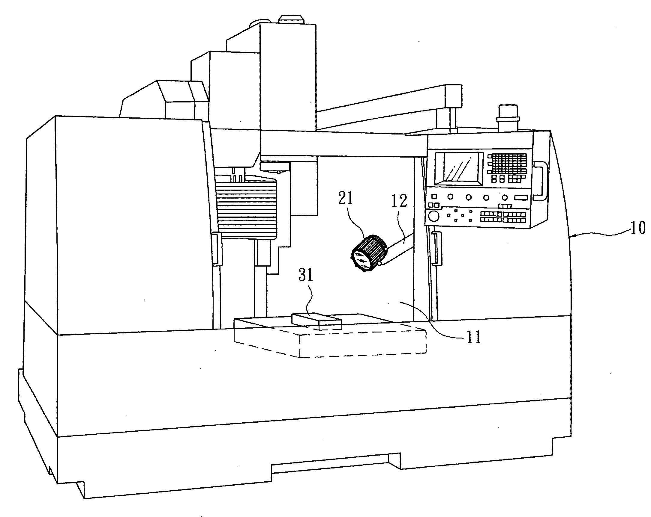
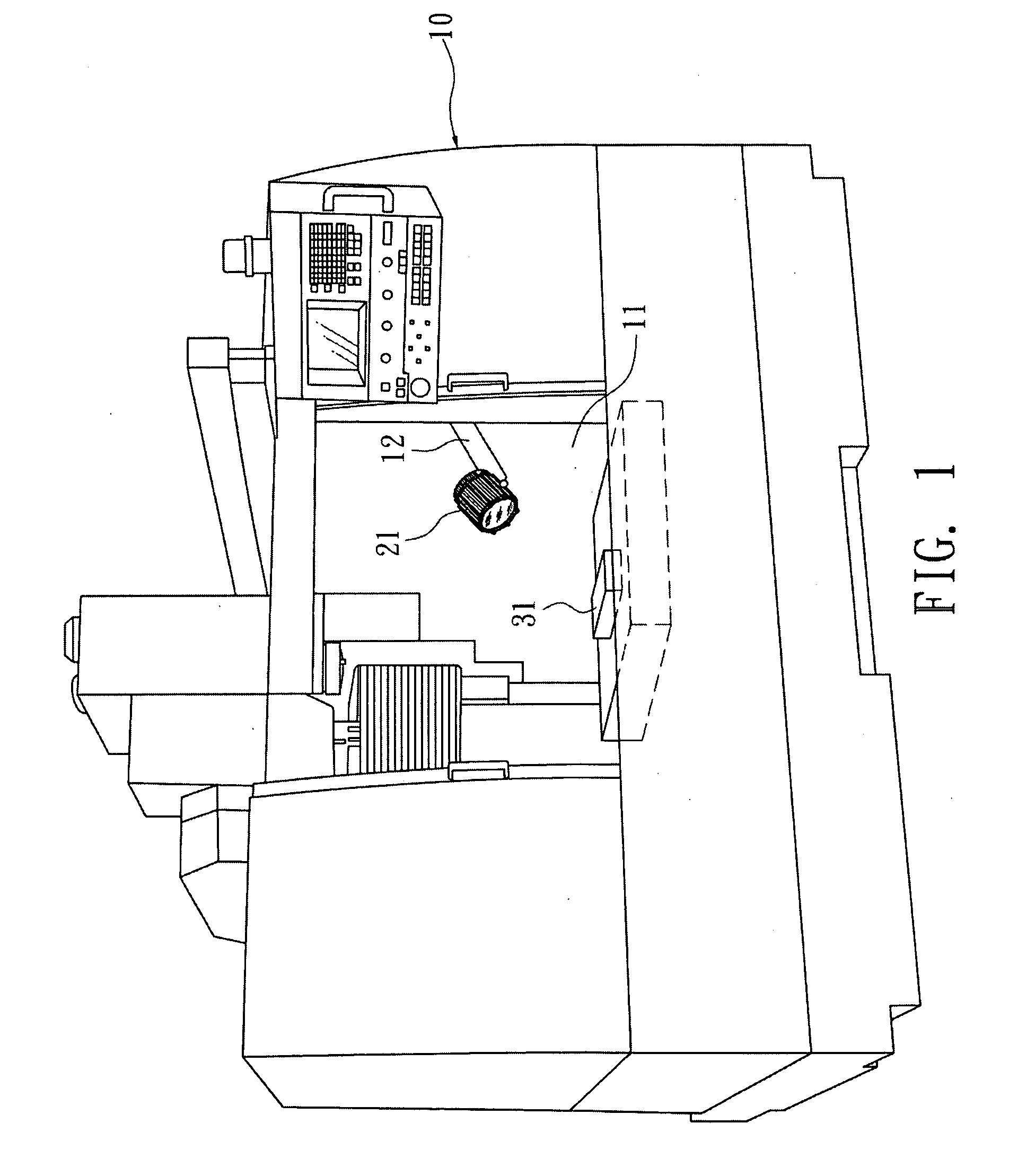
[0029]Please refer to FIG. 1. The illuminating device for tools according to the invention has a machining area 11 in a tool 10. An object 31 to be processed is disposed in the machining area 11 to go through a machining process. An illuminating device 21 uses the LED as its light source for illumination. It is pivotally connected to one arm 12 in the machining area 11, so that the illuminating device 21 can modify its angle to change the light-emitting direction thereof. The light emitted by the illuminating device 21 can thus directly hit the object 31.

[0030]The light-emitting principle of the LED is to produce photons by combining the electrons and holes in a semiconductor. Unlike the usual halogen light bulb that produces a lot of heat while working and unlike the fluorescent ligh...


PUM


Abstract

An illuminating device for machining tools is disclosed. A machining tool is installed with an illuminating device that uses a single LED prepared using the multi chip single module technique to provide high-power light. This elongates the lifetime of the illuminating device and has the advantages of power-saving and low temperature. The light thus produced does not have UV and IR components. In addition to no radiation injury to human bodies, the invention also avoids overlapped shadows in the case of multiple LED sources. Such a design of the cold and single light source can effectively bad influences on the precision of objects 31 being processed.

Description

BACKGROUND OF THE INVENTION[0001]1. Field of Invention[0002]The invention relates to a device for tools and, in particular, to an illuminating device for tools.[0003]2. Related Art[0004]As shown in FIG. 6, a usual tool 1 (e.g., CNC lathe or some machining tool) often includes a halogen light bulb 2 to illuminate an object 3 during the machining process. Its operator can readily observe how the process is going. Even though the halogen light bulb 2 is cheap, such an illuminating means has the following disadvantages:[0005]1. The conventional halogen light bulb consumes too much electrical power. Each one consumes about 50 W power on the average. The cost in electricity after a long time of usage will not be cost-effective.[0006]2. The lifetime of the conventional halogen light bulb is short and about 2000 hours on the average. That means it burns out and needs to be replaced after 3 to 5 months.[0007]3. When illuminating, a conventional halogen light bulb produces a lot of heat, resu...

Claims


Application Information

Patent Timeline
Patent Type & Authority Applications(United States)
IPC IPC(8): F21V33/00
CPCB23Q17/2404F21V5/002F21V13/04F21V29/004F21V29/773F21Y2101/02F21V29/713F21V29/74F21V29/75F21W2131/403F21V5/04F21Y2115/10
Inventor CHEN, KIMBLE J.CHERN, SHYH TAHLU, SHAO-YUKUO, CHI-WENCHANG, SUNG-CHIHSU, JUI-WEICHUANG, YU-KU
Owner AVEX SG TECH
Why Eureka
Try Eureka