Toner fixing apparatus and electrophotographic printing device

a technology of electrophotographic printing and fixing apparatus, which is applied in the direction of electrographic process apparatus, instruments, optics, etc., can solve the problems of affecting paper transfer, reducing heating efficiency, and limiting methods, and achieves short time, efficient drying performance, and reduction of heating efficiency

Inactive Publication Date: 2010-04-08
MIYAKOSHI PRINTING MACHINERY
View PDF8 Cites 15 Cited by
  • Summary
  • Abstract
  • Description
  • Claims
  • Application Information

AI Technical Summary

Benefits of technology

[0011]According to the present invention, the drying and removal (drying by vaporization of volatile components) of carrier liquid by irradiation with infrared radiation to the web in the provisional fixing portion is performed using frictional heat resulting from internal vibrations within the carrier liquid resulting from the optical energy of infrared radiation from a heat source mainly used for toner fixing operations. As the application of a heating method which applies heat to fix toner by internal vibration of the carrier liquid as a result of optical energy, it is possible to avoid the disadvantages that the residence of heated air involves heating efficiency (reduction in heating efficiency) (for example, refer to Japanese Patent Application Laid-Open No. 2-51353). Drying and removal of carrier liquid by irradiation of the web with infrared radiation is a heating method which applies heat directly to the carrier liquid using infrared optical energy. Consequently drying and removal of carrier liquid (vaporization removal) can be realized in a short time in comparison with drying and removal by application of heated air. Since the provisional fixing portion enables efficient performance of drying and removal of a carrier liquid, downsizing of the device is realized easily, the toner fixing apparatus and electrophotographic printing device can be downsized for more effective use of space. The occurrence of paper creasing and stretching is suppressed in comparison with vaporization removal of carrier liquid by application of high temperature heated air and has the advantage that smooth paper transfer can be maintained. Furthermore, application of a heating method using infrared radiation causes the heated object to reach a target temperature in a short time and therefore enables highly efficient operation. Thereby, damage to paper can be reduced by application of this type of short-term heat application. Furthermore, easy management of the fixing apparatus and improvement of control operation performance are enabled in comparison to drying and removal by application of heated air in accordance with a conventional method. Consequently production efficiency can be improved by better production management. Since fixing operations are performed by a two-step process including provisional fixing by irradiation with infrared radiation in a provisional fixing portion (provisional fixing by vaporization drying of the carrier liquid) and main fixing by application of heat and pressure using a heat roller in a main fixing portion, damage to the recording medium (web) caused by rapid application of pressure and heat can be suppressed in comparison with a one-step fixing operation of heat and pressure without performing a provisional fixing operation. Consequently good drying and fixing and printing quality can be ensured even during high-speed processing. Disadvantages related to the effect of web damage on transfer performance can be avoided and smooth paper transfer can be maintained.
[0012]When air flow along the web is formed by the air flow formation apparatus according to the second aspect in order to discharge carrier-liquid vapor vaporized from the web, a further reduction in time for drying by vaporization of the carrier liquid can be realized. In addition, further suppression of paper creasing and stretching of paper can be ensured. Since residence of vapor components from residual toner or vaporized carrier liquid is prevented and vapor discharge is performed in a smooth manner, environmental contamination can be effectively prevented. Furthermore, the effect on peripheral environmental areas and equipment due to residence of vapor components can be prevented.

Problems solved by technology

However this method has limitations resulting from the contact time and the contact temperature with the printed surface.
(a) The above-mentioned non-contact hot-air fixing device places the heated air in contact with the paper by discharging heated air from a plurality of through holes provided in a plate-shaped heater body. However an increase in the contact area of the heated air for the paper and elongation of the device to ensure contact time has an adverse effect on the performance of air discharge from through holes in proximity to a central portion of the heated air blow region (region connected with the heater body). Thereby, the heating efficiency is reduced due to the absence of heated air circulation and contamination results from delay of vapor components in residual toner.
(b) When the temperature of heated air is increased to improve fixing properties, stretching or creasing of the paper results from excess heat and affects paper transfer.
(c) The length of the fixing apparatus is increased proportional to the number of colors and results in an increase in the overall size of the apparatus and consequently causes problems associated with installation space.

Method used


Image

  • Toner fixing apparatus and electrophotographic printing device
  • Toner fixing apparatus and electrophotographic printing device
  • Toner fixing apparatus and electrophotographic printing device

Examples


Embodiment Construction

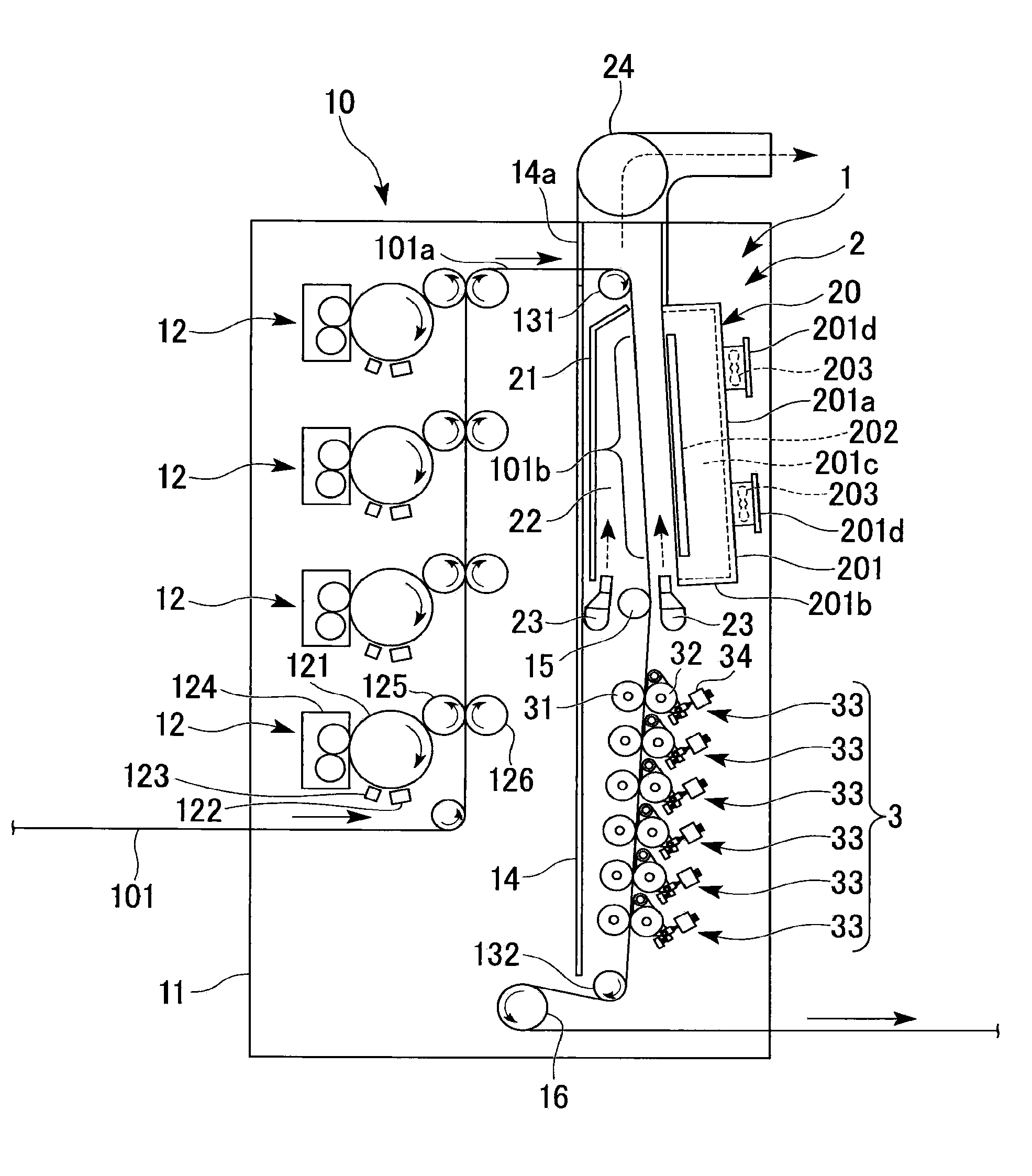
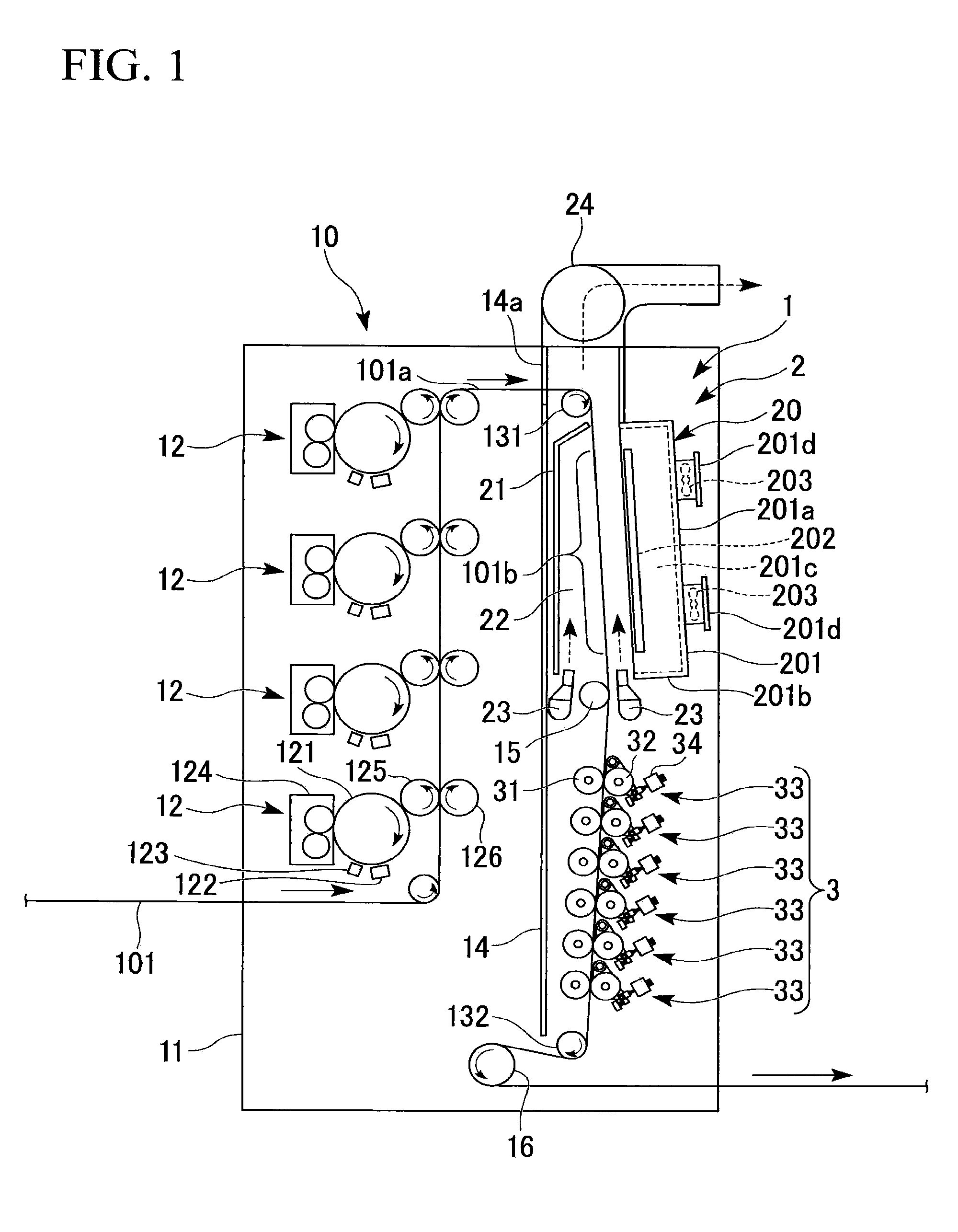
[0017]The preferred embodiments of a toner fixing apparatus and electrophotographic printing device according to the present invention will be described hereafter making reference to the figures. FIG. 1 is a front view showing an electrophotographic printing device 10 applying a toner fixing apparatus 1 according to the present invention. FIG. 2 shows the arrangement of the provisional fixing components 20 of the toner fixing apparatus 1 seen from an open side. FIG. 3 shows the arrangement of a main fixing unit 33 of a main fixing portion 3 of a toner fixing apparatus 1. FIG. 4 is a sectional view showing the structure of the main fixing unit 33 as shown in FIG. 3. In FIG. 1 to FIG. 4, an upper side will be described as upper and a lower side will be described as lower.

[0018]The electrophotographic printing device 10 shown in FIG. 1 is provided with an electrophotographic printing unit 12 provided on upper and lower multiple stages (in the figure, 4 stages are shown) to perform mult...


PUM


Abstract

A toner fixing apparatus characterized by provision of a provisional fixing portion provided with a provisional fixing component having an infrared heater irradiating infrared radiation onto a printed surface of the web and a main fixing portion provided downstream in the web flow in the provisional fixing portion and nipping the web with heat rollers performing a main fixing operation or having a plurality of main fixing units. According to this invention, a toner fixing apparatus and an electrophotographic printing device including the toner fixing apparatus are provided which display excellent fixing properties during multicolor image formation, excellent heating efficiency and excellent economy with respect to installation space.

Description

BACKGROUND OF THE INVENTION[0001]1. Field of the Invention[0002]The present invention relates to a toner fixing apparatus for a wet-type electrophotographic printing device using a developing liquid composed of a liquid toner and a carrier liquid, and to an electrophotographic printing device provided with the toner fixing apparatus. The present application claims priority from Japanese Patent Application No. 2008-258818, filed Oct. 3, 2008, the content of which is incorporated herein by reference.[0003]2. Description of the Related Art[0004]In an imaging system using a developing liquid composed of a liquid toner (hereafter “toner”) and a carrier liquid, the carrier liquid is absorbed by paper when transferring a toner image transcribed onto an intermediate transfer body onto the paper. When the paper passes through a plurality of units provided with an intermediate transfer body to form a multicolored image, the paper contains several color components and a large amount of carrier...

Claims


Application Information

Patent Timeline
Patent Type & Authority Applications(United States)
IPC IPC(8): G03G15/20
CPCG03G15/10G03G15/2032G03G2215/2006G03G15/2007
Inventor IZAWA, HIDEOSETOYAMA, JUNICHIOOYAMA, KOUICHIHARADA, KOTARO
Owner MIYAKOSHI PRINTING MACHINERY
Why Eureka
Try Eureka