Switch circuit

a switch circuit and switch technology, applied in the field of switches, can solve the problem of a large number of ports, and achieve the effect of increasing the number of switches assigned

Active Publication Date: 2010-04-15
SATURN LICENSING LLC
View PDF3 Cites 19 Cited by
  • Summary
  • Abstract
  • Description
  • Claims
  • Application Information

AI Technical Summary

Benefits of technology

[0027]According to the embodiments of the present invention, all possible combinations of statuses of the keys are distributed along the time axis. This makes it p

Problems solved by technology

However, the first and second examples have a drawback in that the numbe

Method used


Image

  • Switch circuit
  • Switch circuit
  • Switch circuit

Examples


first embodiment

1. First Embodiment

Configuration of the First Embodiment

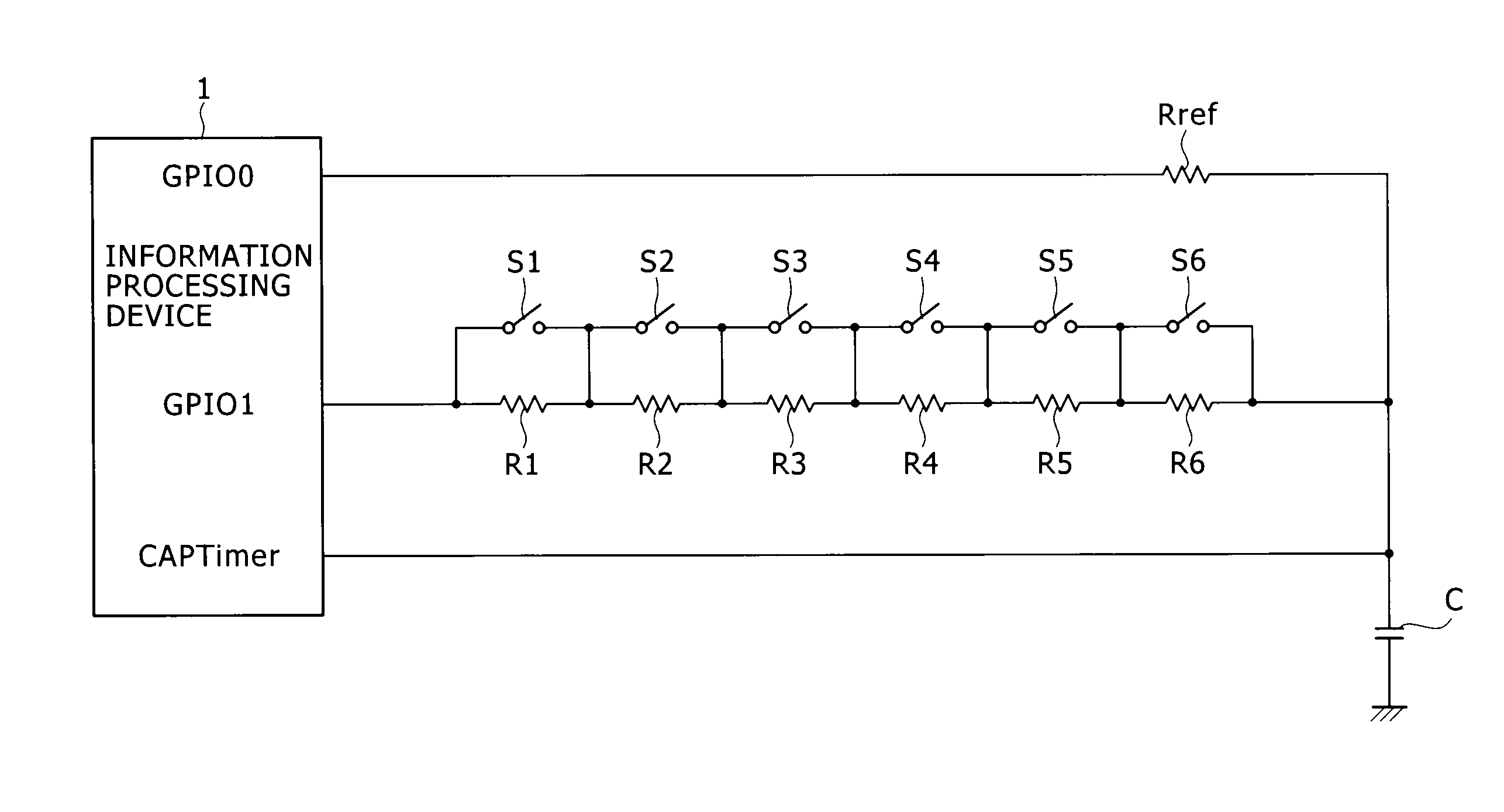
[0049]FIG. 5 illustrates the configuration of a first embodiment of the present invention. The information processing device 1 includes three general-purpose I / O ports, namely, GPIO0, GPIO1 and CAPTimer. The general-purpose I / O ports handle high- or low-level inputs or outputs. Whether the I / O ports function as input or output ports is specified by the CPU (Central Processing Unit) which functions as a control section of the information processing device 1.

[0050]That is, each of the I / O ports is selectively specified by the CPU of the information processing device 1 to be in input or output state. When the I / O port is in output state, the specified level, i.e., high or low level, is output from the I / O port. When the I / O port is in input state, the I / O port is in high impedance state. When the I / O port is in high impedance state, the capacitor terminal voltage of the charge / discharge circuit is measured.

[0051]An example of the...

second embodiment

[0072]As illustrated in FIG. 9, each of the I / O ports GPIO0 and GPIO1 is used as the I / O port CAPTimer, thus providing a reduced number of ports. A diode D is connected in parallel with the reference resistor Rref. The diode D has its anode connected to the capacitor C and its cathode connected to the I / O port GPIO0.

Operation of the Second Embodiment

[0073]A description will be given below of the operation of the second embodiment of the present invention with reference to FIG. 10. FIG. 10 illustrates the states of the I / O ports GPIO0 (CAPTimer0) and GPIO1 (CAPTimer1). Further, FIG. 10 illustrates the change of the terminal voltage of the capacitor C. Each port is specified by the CPU of the information processing device 1 to be in output or input state. When in output state, the I / O port outputs high or low level. When in input state, the I / O port is in high impedance state. In FIG. 10, the periods of the waveforms during which the ports are in output state are shown by bold lines,...

third embodiment

[0081]As illustrated in FIG. 11, the third embodiment is similar to the first embodiment in that the I / O ports GPIO0, GPIO1 and CAPTimer are used. A capacitor is provided for each of the two charge / discharge circuits, i.e., a capacitor C11 for the reference charge / discharge circuit and a capacitor C12 for the charge / discharge circuit to be measured. The capacitors C11 and C12 are adjusted to have the same capacitance. The difference in capacitance between the capacitors C11 and C12 is cancelled by signal processing (software processing).


PUM


Abstract

A switch circuit includes: a first charge/discharge circuit having a fixed first time constant; a second charge/discharge circuit having a second time constant associated with the operation statuses of a plurality of switches; first and second input/output ports to which the first and second charge/discharge circuits are connected, respectively; and a control section adapted to measure the first and second time constants by charging or discharging the first and second charge/discharge circuits and determine the operation statuses of a plurality of switches based on the ratio of the measured first and second time constants.

Description

BACKGROUND OF THE INVENTION[0001]1. Field of the Invention[0002]The present invention relates to a switch circuit which includes a plurality of switches and an information processing device for detecting operation statuses of the switches.[0003]2. Description of the Related Art[0004]A plurality of key switches are provided on the operation panel of electronic equipment such as television set or within the casing thereof. The operation statuses of the key switches are determined, for example, by an information processing device such as embedded microcomputer. The term “operation statuses of the key switches” refers to the ON / OFF statuses of the key switches. Unlike general-purpose computers, embedded microcomputers are designed primarily to control equipment and incorporate I / O (input / output) ports, an A / D (analog-to-digital) converter, a D / A (digital-to-analog) converter and other components in addition to a CPU (Central Processing Unit).[0005]A first example of a known switch circu...

Claims


Application Information

Patent Timeline
IPC IPC(8): H03K17/00
CPCH03M11/24
Inventor NAKADA, MITSURUTAKESUE, MASAAKI
Owner SATURN LICENSING LLC
Why Eureka
Try Eureka