Fiber optic sensor head and interferometric measuring system

a sensor head and fiber optic technology, applied in the direction of optical radiation measurement, instruments, spectrometry/spectrophotometry/monochromators, etc., can solve the problems of comparatively space-consuming michelson or mireau interferometers for measuring probes and/or reference probes provided in the cited patent application, and achieve economic and space-saving effects

Inactive Publication Date: 2010-04-15
ROBERT BOSCH GMBH
View PDF3 Cites 4 Cited by
  • Summary
  • Abstract
  • Description
  • Claims
  • Application Information

AI Technical Summary

Benefits of technology

[0008]An object of the present invention is to provide a probe and an interferometric measuring system which, in addition to the advantages stated at the outset, may also be impleme

Problems solved by technology

However, the Michelson or Mireau interferometers for the measuring probe and/or reference probe provided in the cited patent application have prov

Method used


Image

  • Fiber optic sensor head and interferometric measuring system
  • Fiber optic sensor head and interferometric measuring system
  • Fiber optic sensor head and interferometric measuring system

Examples


Embodiment Construction

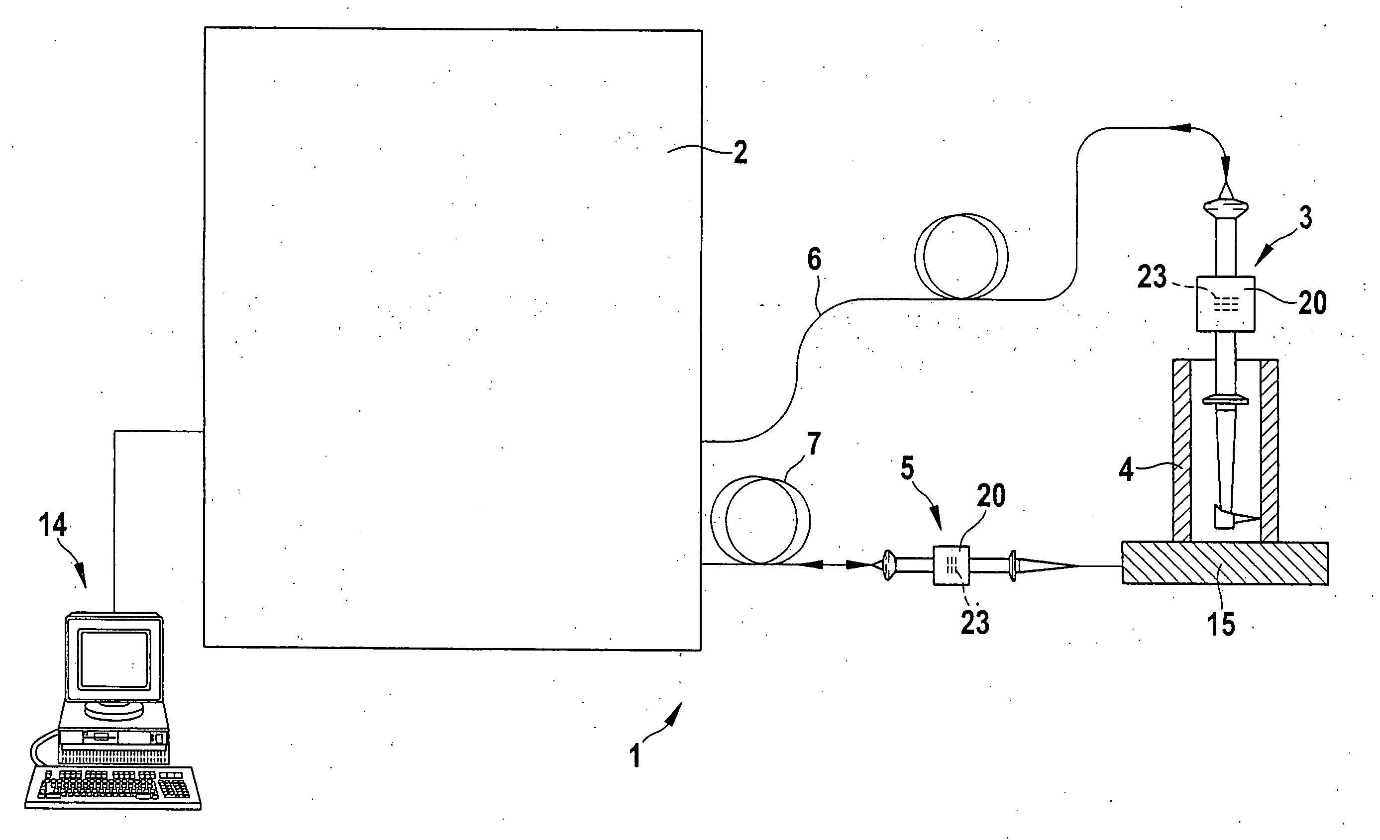
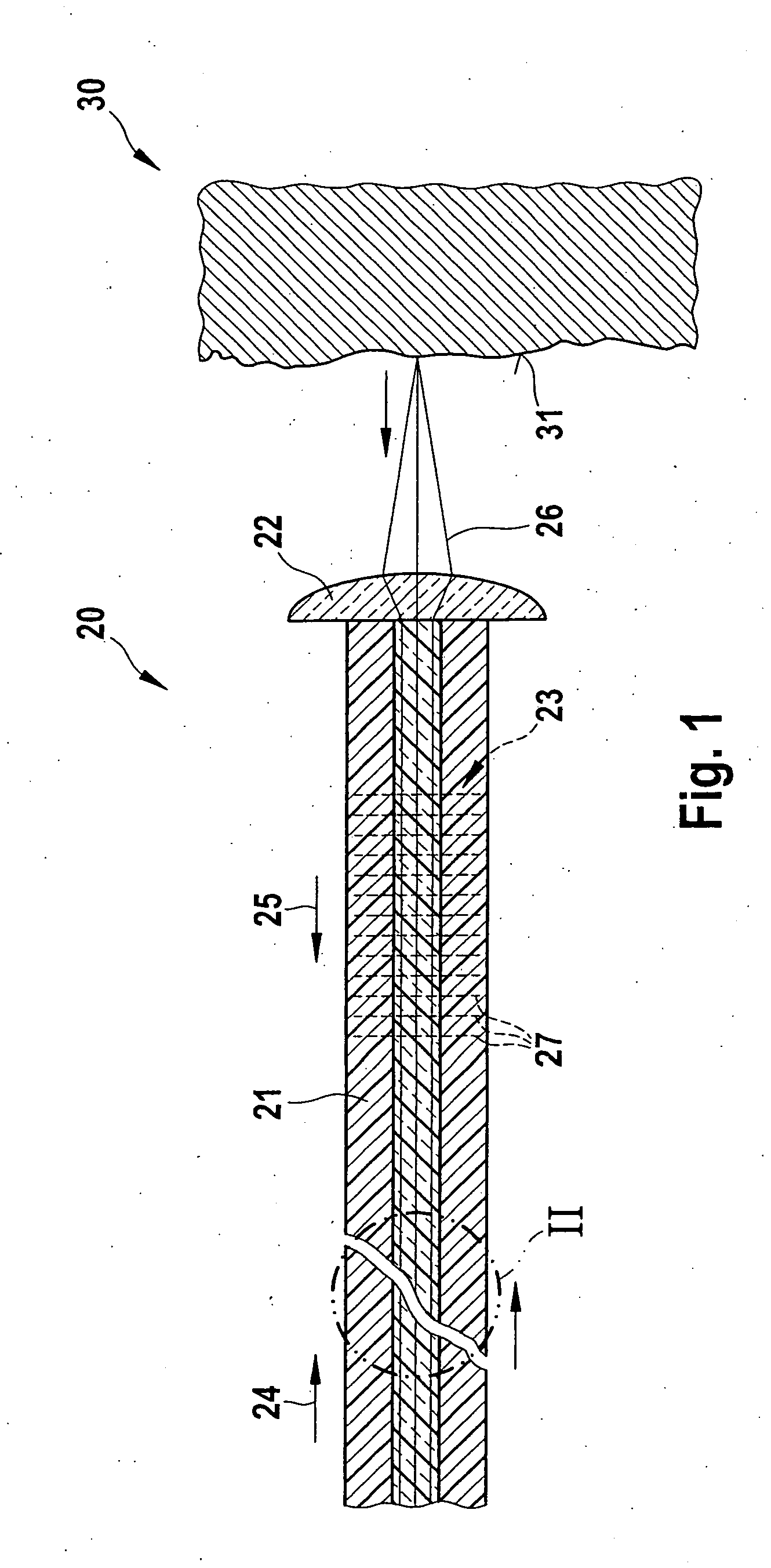
[0022]FIG. 1 shows a fiber optic sensor head 20 of the type which is particularly suited for detecting the shape or the distance of a test object 30, in particular a of a rough surface 31 of test object 30 as shown here. Fiber optic sensor head 20 has proven to be particularly suitable for an interferometric measuring system 1, as illustrated in greater detail in FIG. 3.

[0023]Fiber optic sensor head 20 has an optical fiber 21, which in the present case is designed as a glass fiber, for conducting and returning two partial beams 24, 25 to and from test object 30, and a lens 22 on the test object side which is used for injecting and extracting a ray beam 26 formed in optical fiber 21 by partial beams 24, 25. Lens 22 is schematically illustrated.

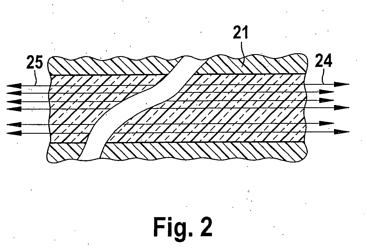
[0024]In the enlarged detail of optical fiber 21 illustrated in FIG. 2, partial beams 24, 25 are symbolically represented by arrows. The length of the arrows indicates the phase position of partial beams 24, 25. It is understood that, even when...


PUM


Abstract

A fiber optic sensor head for detecting the shape or the distance of a test object has an optical fiber, in particular a glass fiber, for conducting and returning partial beams to and from the test object, and an injection/extraction lens on the test object side. For conducting partial beams, injected on the sensor head side and having an optical path length difference, to the test object and returning partial beams injected on the test object side without an optical path length difference, a Fizeau interferometer having a nondiscrete design is associated with the optical fiber and compensates for the optical path length difference between the partial beams.

Description

BACKGROUND OF THE INVENTION[0001]1. Field of the Invention[0002]The present invention relates to a fiber optic sensor head for detecting the shape or the distance a test object, the sensor head having an optical fiber for conducting and returning two partial beams to and from the test object and an injection / extraction lens on the test object side. The present invention further relates to an interferometric measuring system for detecting the shape or the distance of a test object, having a unit designed as a modulation interferometer and configured for generating two partial beams having an optical path length difference, and having a measuring probe and / or a reference probe.[0003]2. Description of Related Art[0004]Such an interferometric measuring system is described in published German patent document DE 198 08 273 by the present applicant. This and other types of interferometric measuring systems are particularly suited for interferometrically measuring rough surfaces of a measur...

Claims


Application Information

Patent Timeline
IPC IPC(8): G01B9/02G01B11/02
CPCG01B11/007G01B11/303G01B9/0205G01B9/02057G01B9/02002G01B9/0201
Inventor FRANZ, GERALD
Owner ROBERT BOSCH GMBH
Why Eureka
Try Eureka