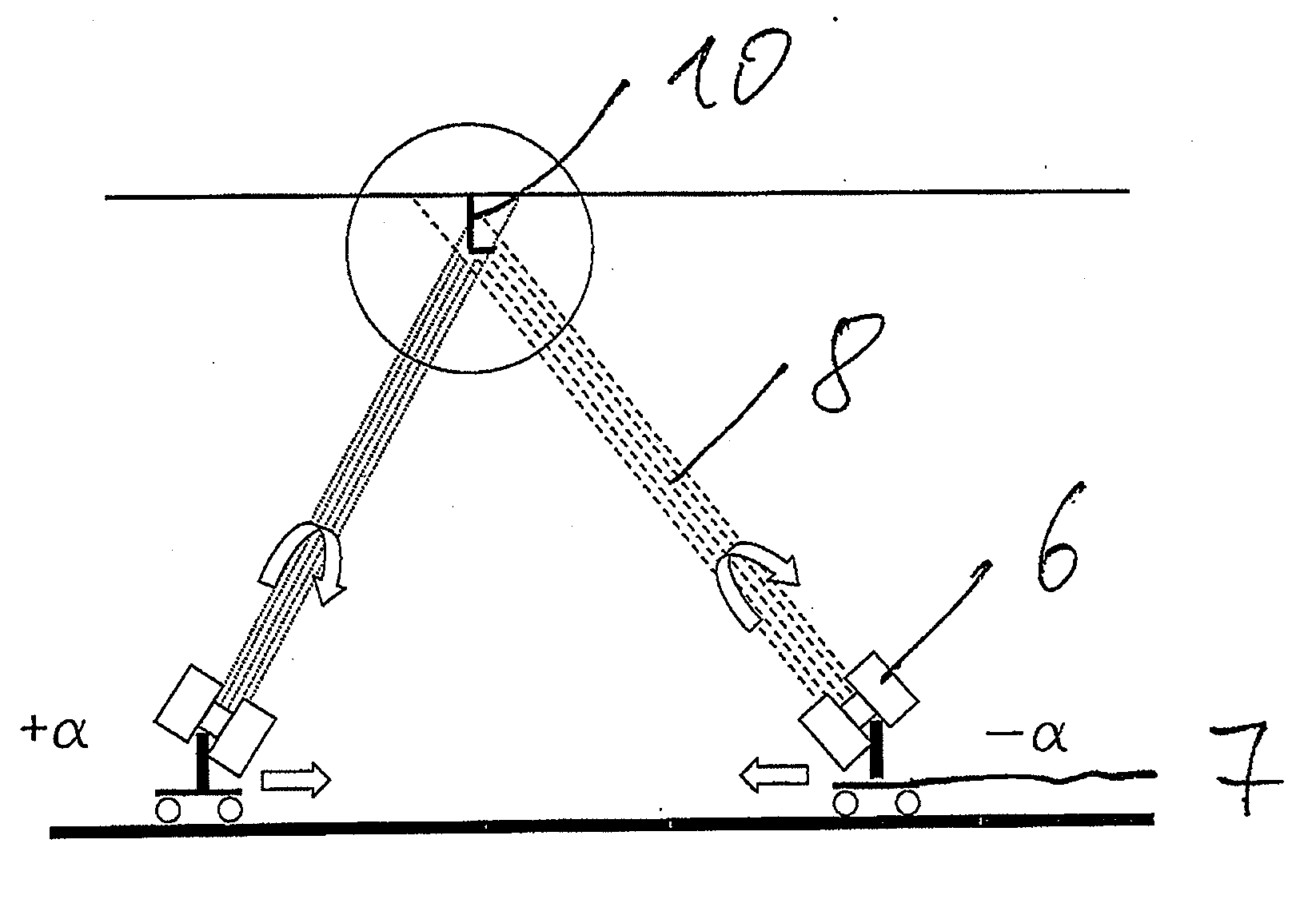
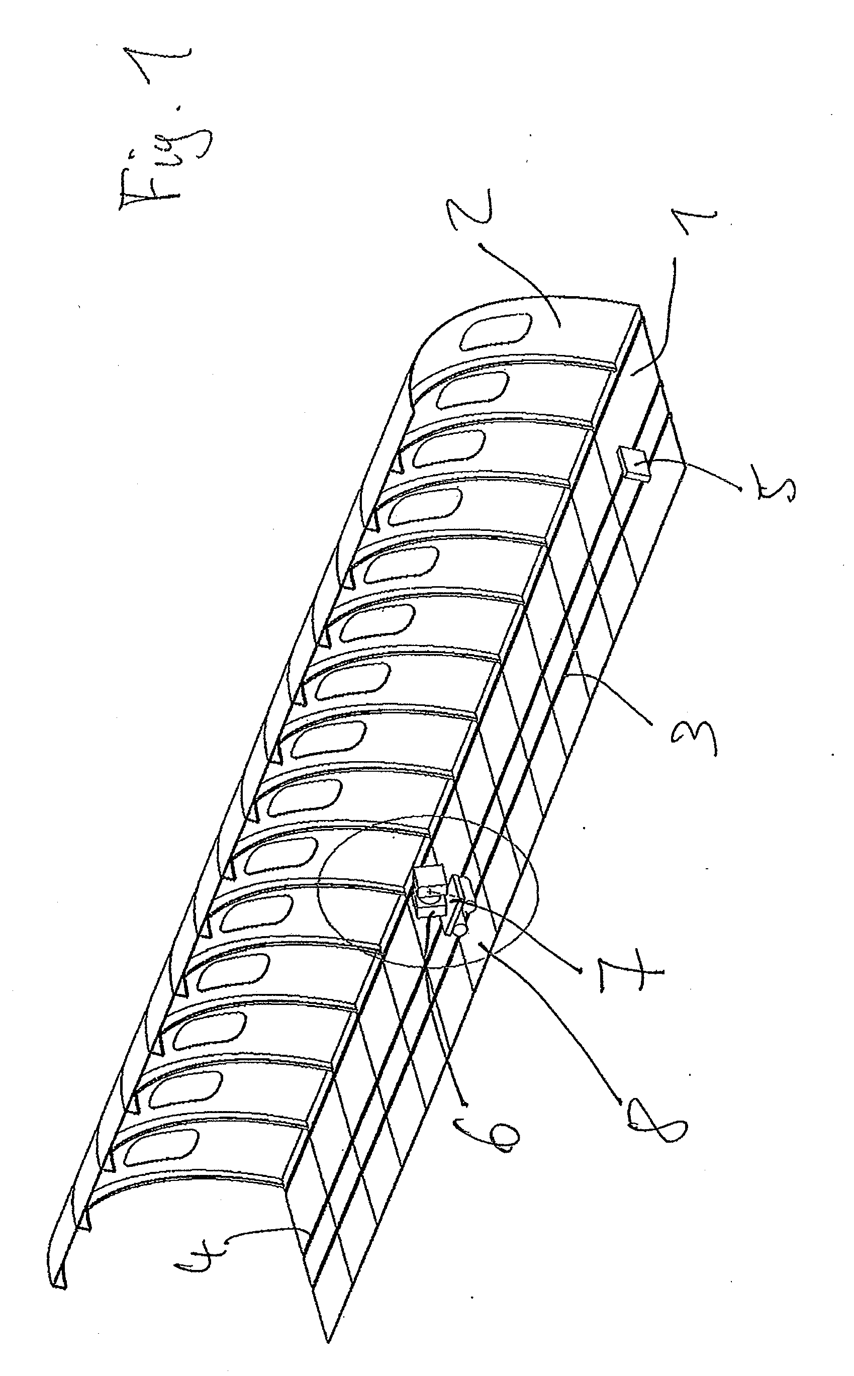
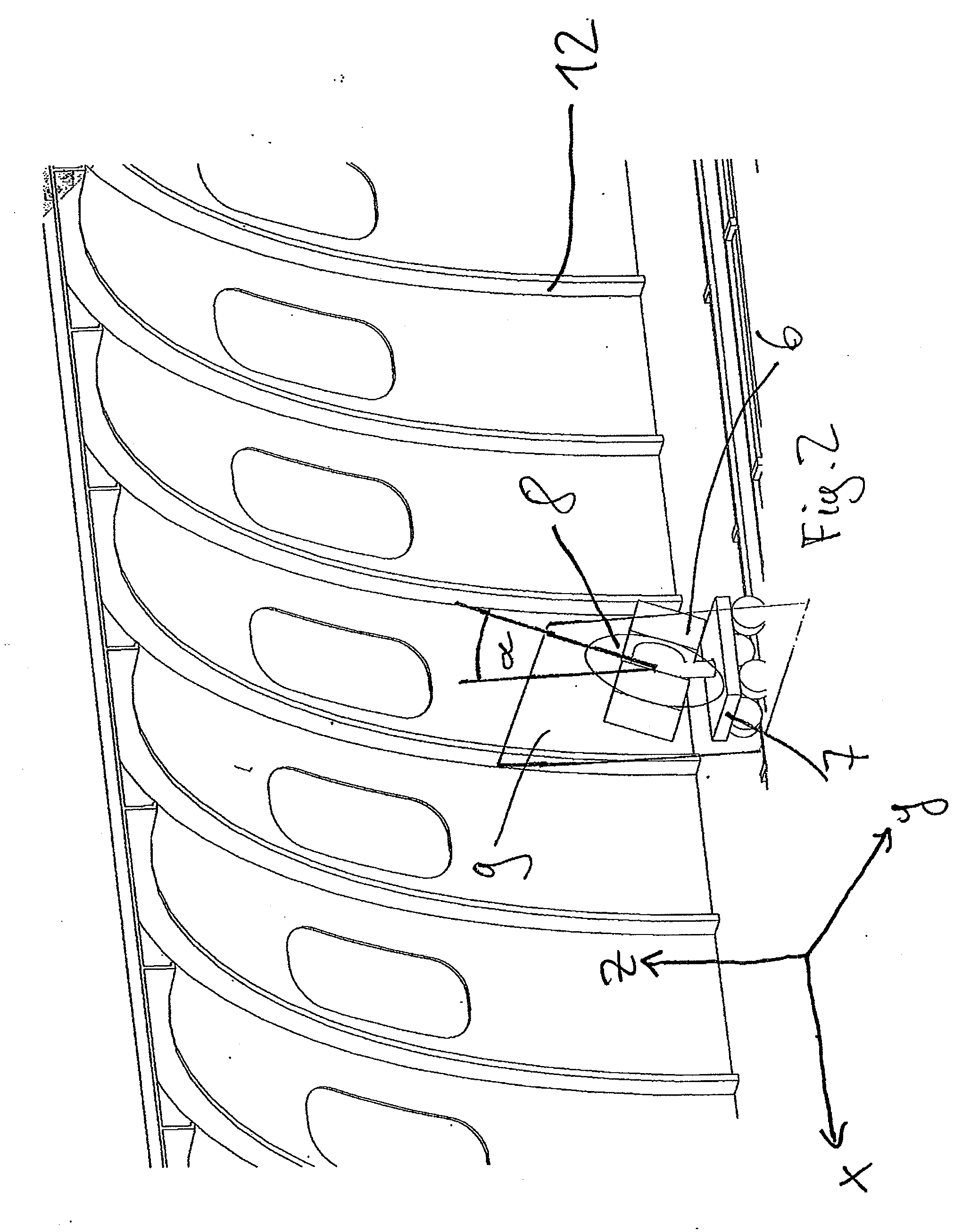
[0006]The invention is based on the object of providing a method of the type mentioned in the introduction, which allows a measurement of in particular elongate internal spaces which is simple and of high quality. The invention achieves said object by tilting the scan plane about the y-axis by a tilt angle α and / or about the z-axis by a tilt angle γ, preferably about the y-axis and the z-axis, out of the
global coordinate system of the internal space.
[0007]It is possible, according to the invention, to efficiently measure with largely homogeneous resolution a typically approximately cylindrical internal space for example of an aircraft. Since both
angle of incidence and distance of incidence of the measurement beam onto the regions to be measured are subject to less variation than in the case of the spherical scan of the prior art, the method according to the invention has an assessable and relatively small measurement error. The point clouds themselves, which are obtained by the measurements, are impractical in data-technology terms and only difficult to manage. According to the invention, so-called meshes are produced on the basis thereof preferably by a so-called meshing operation, with the meshes describing the internal space measured and being used as the basis for further
processing. Due to its homogeneous and relatively small error and owing to extensive illumination even of undercuts, as described below, the invention allows the provision of good base data for the calculation of such a mesh.
[0010]Tilting said scan plane has the
advantage that any undercuts in the surface to be scanned can in this way be illuminated better. By aligning the scan plane at an
oblique angle relative to the yz-plane, the measurement beams strike the frequently approximately cylindrical surface of the internal space not at a right angle, but at an angle which depends on the tilting of the scan plane. Unlike in a so-called spherical scan, however, said angle is substantially the same across the entire internal space to be measured, with the result that the measurement accuracy for all regions of the internal space is also substantially consistent.
[0014]The location of the laser
scanner during a measurement in the coordinate
system of the internal space to be measured must be known in order to evaluate the measurement results. According to the invention, a means, which is already known in the prior art, for location and orientation tracking of the laser
scanner in the internal space is used for this purpose. In the case of manually securing the laser scanner between the measurements, the laser scanner can be positioned for each measurement at a previously defined and thus known location. If the laser scanner is preferably arranged on a vehicle, some of the spatial coordinates of the laser scanner can already be pre-specified by the rail-bound guidance of the travel path. Further spatial coordinates on the movement path can be determined, for example, by mechanical systems which detect and evaluate, for example, markings on the travel path or have wheel rotary
transmitter sensors on the vehicle. By way of example, inclination sensors, which detect inclination, tilting or yawing while the vehicle is moved, may additionally be present. The measurement accuracy can be significantly enhanced also by the detection of such inclination, tilting and yawing movements.
[0018]Conventional transport means such as aircraft are frequently mirror-symmetrical with respect to an xz-plane of their coordinate
system, that is to say a
mirror plane which extends through the longitudinal axis and
vertical axis. It is possible within the context of the invention to arrange the travel path of the laser scanner centrally in the internal space, that is to say such that it extends in the
mirror plane. It is, however, also possible according to the invention to move in the two scans the scanner on different travel paths, for example on different sides of such a
mirror plane, if it is present. It is possible in particular that the two travel paths are straight lines which are mutually parallel and extend substantially mirror-symmetrically with respect to the mirror plane xz of the internal space. It is also possible according to the invention, however, for the two travel paths or movement axes to have different distances from the center line of the internal space. In a mirror-symmetrical internal space, said center line extends in the mirror plane xz of the internal space. Moving the laser scanner in this manner on two travel paths at a distance from the center axis of the internal space facilitates the illumination even of undercuts which extend laterally (in the direction of the y-axis).
[0032]An arrangement according to the invention for carrying out the method can have a base with travel paths (for example rails) for a laser scanner which are arranged thereon, which has means for connecting to the seat rails in the cabin floor of a transport means, such as an aircraft. It is possible in this manner for the travel path of the laser scanner to be mounted quickly and easily into a defined position in an aircraft. It is preferred according to the invention if the laser scanner can carry out the measurement method autonomously in the absence of operating staff. This avoids the occurrence of torsions or other deformation of the structure to be measured caused for example by the presence of operating staff in the aircraft cabin. It is further preferred if the laser scanner is also autonomous with respect to the power supply and carries a power source such as a battery. As an alternative, power may be supplied for example by way of the travel path (for example the rails).


