Magnetic stack having reduced switching current

a technology of switching current and magnetic stack, applied in the direction of magnetic bodies, instruments, solid-state devices, etc., can solve the problems of flash memory (nand or nor) also facing scaling problems, slow access speed, limited endurance,

Inactive Publication Date: 2010-04-15
SEAGATE TECH LLC
View PDF100 Cites 16 Cited by
  • Summary
  • Abstract
  • Description
  • Claims
  • Application Information

AI Technical Summary

Benefits of technology

[0005]The present disclosure relates to a magnetic stack, such as a spin torque memory cell, or magnetic tunnel junction cell, that includes a material which is antiferromagnetic at low temperatures and paramagnetic at high temperatures.

Problems solved by technology

Current technology like flash memory has several drawbacks such as slow access speed, limited endurance, and the integration difficulty.
Flash memory (NAND or NOR) also faces scaling problems.
Also, traditional rotating storage faces challenges in increasing areal density and in making components like reading / recording heads smaller and more reliable.
As the MTJ size shrinks, the switching magnetic field amplitude increases and the switching variation becomes more severe.
However, many yield-limiting factors must be overcome before such magnetic stacks can reliable be used as memory devices or field sensors.

Method used


Image

  • Magnetic stack having reduced switching current
  • Magnetic stack having reduced switching current
  • Magnetic stack having reduced switching current

Examples


Embodiment Construction

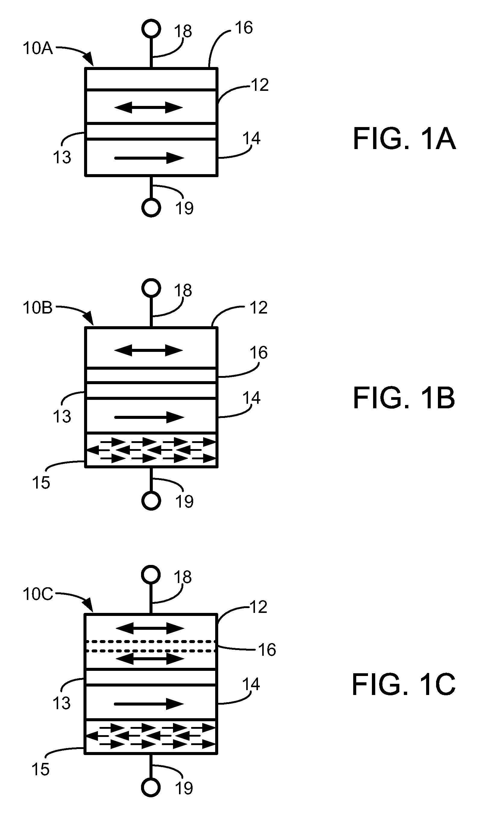
[0014]This disclosure is directed to magnetic stacks (e.g., spin torque memory (STRAM) cells and read sensors) that include a material that at low temperature is antiferromagnetic but at high temperature is paramagnetic. By including such a material layer proximate the free layer in a magnetic stack, the thermal stability of the stack can be maintained, and even providing lower switching current in memory cell embodiments.

[0015]In the following description, reference is made to the accompanying set of drawings that form a part hereof and in which are shown by way of illustration several specific embodiments. It is to be understood that other embodiments are contemplated and may be made without departing from the scope or spirit of the present disclosure. The following detailed description, therefore, is not to be taken in a limiting sense. Any definitions provided herein are to facilitate understanding of certain terms used frequently herein and are not meant to limit the scope of t...


PUM


Abstract

A magnetic stack having a ferromagnetic free layer, a ferromagnetic pinned reference layer, a non-magnetic spacer layer between the free layer and the reference layer, and a variable layer proximate the free layer. The variable layer is antiferromagnetic at a first temperature and paramagnetic at a second temperature higher than the first temperature. During a writing process, the variable layer is paramagnetic. For magnetic memory cells, such as magnetic tunnel junction cells, the variable layer provides reduced switching currents.

Description

RELATED APPLICATION[0001]This application claims priority to U.S. provisional patent application No. 61 / 104,395, filed on Oct. 10, 2008 and titled “Material for Switching Current Reduction”. The entire disclosure of application No. 61 / 104,395 is incorporated herein by reference.BACKGROUND[0002]Fast growth of the pervasive computing and handheld / communication industry has generated exploding demand for high capacity nonvolatile solid-state data storage devices and rotating magnetic data storage devices. Current technology like flash memory has several drawbacks such as slow access speed, limited endurance, and the integration difficulty. Flash memory (NAND or NOR) also faces scaling problems. Also, traditional rotating storage faces challenges in increasing areal density and in making components like reading / recording heads smaller and more reliable.[0003]Resistive sense memories are promising candidates for future nonvolatile and universal memory by storing data bits as either a hig...

Claims


Application Information

Patent Timeline
Patent Type & Authority Applications(United States)
IPC IPC(8): G11C11/14H01L29/82G11C11/416
CPCB82Y25/00G11C11/16H01F10/3254H01F10/3295H01L27/222H01L43/08H01L43/10H01F10/3268G11C11/1675H10B61/00H10N50/85H10N50/10
Inventor GAO, ZHENGZHENG, YUANKAIXI, HAIWENDIMITROV, DIMITAR V.
Owner SEAGATE TECH LLC
Why Eureka
Try Eureka