

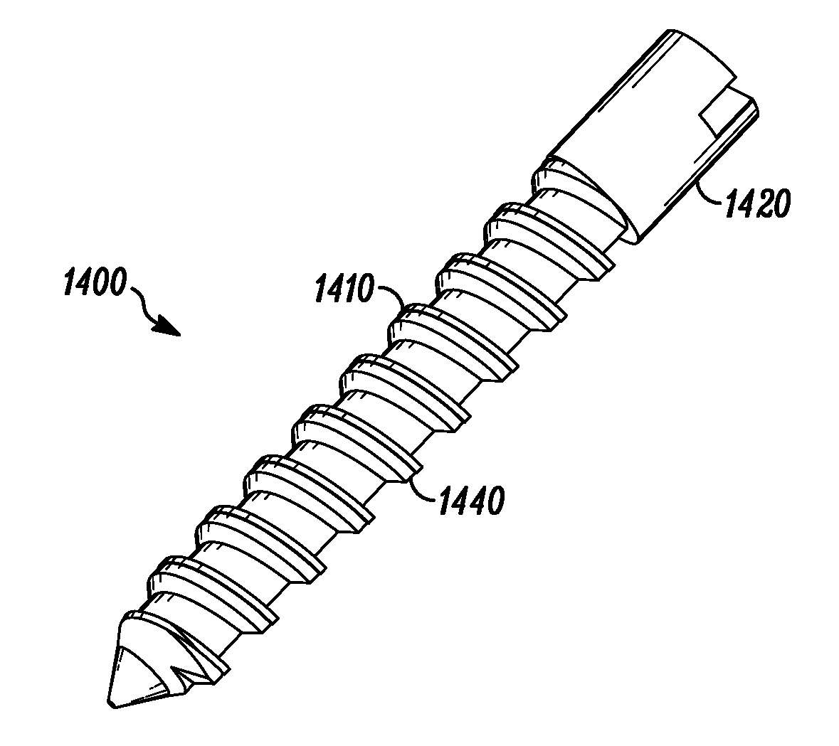
Porous Bone Fixation Device
a bone fixation device and bone technology, applied in the field of bone fixation devices, can solve the problems of fatigue failure, conventional bone fixation devices simply wear unexpectedly quickly, poor bone apposition,
- Summary
- Abstract
- Description
- Claims
- Application Information
AI Technical Summary
Benefits of technology
Problems solved by technology
Method used
Image

Examples
Embodiment Construction
[0042]The present invention relates to porous metal articles having porosity characteristics that are determined by an extractable material which is removed prior to a final sintering and methods to manufacture such porous metal articles.
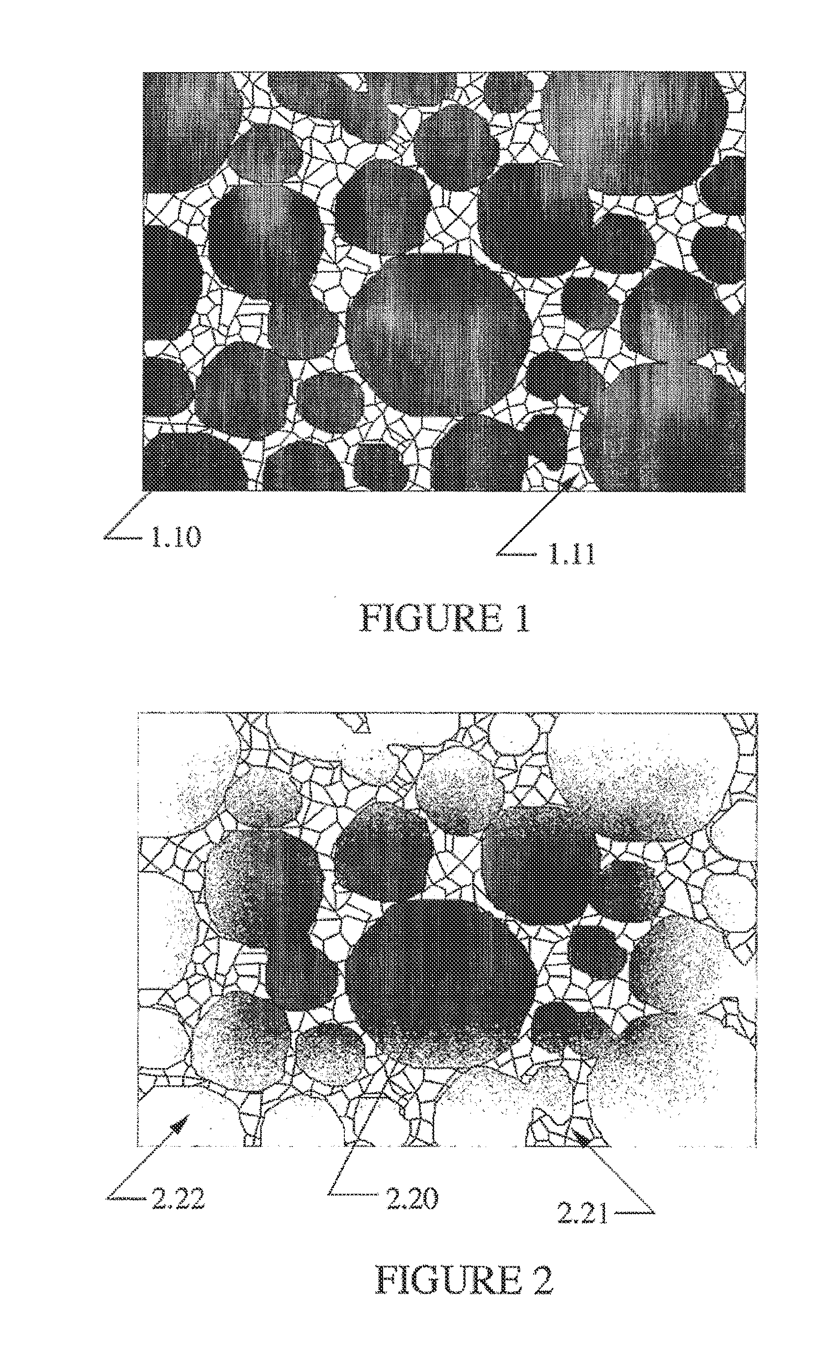
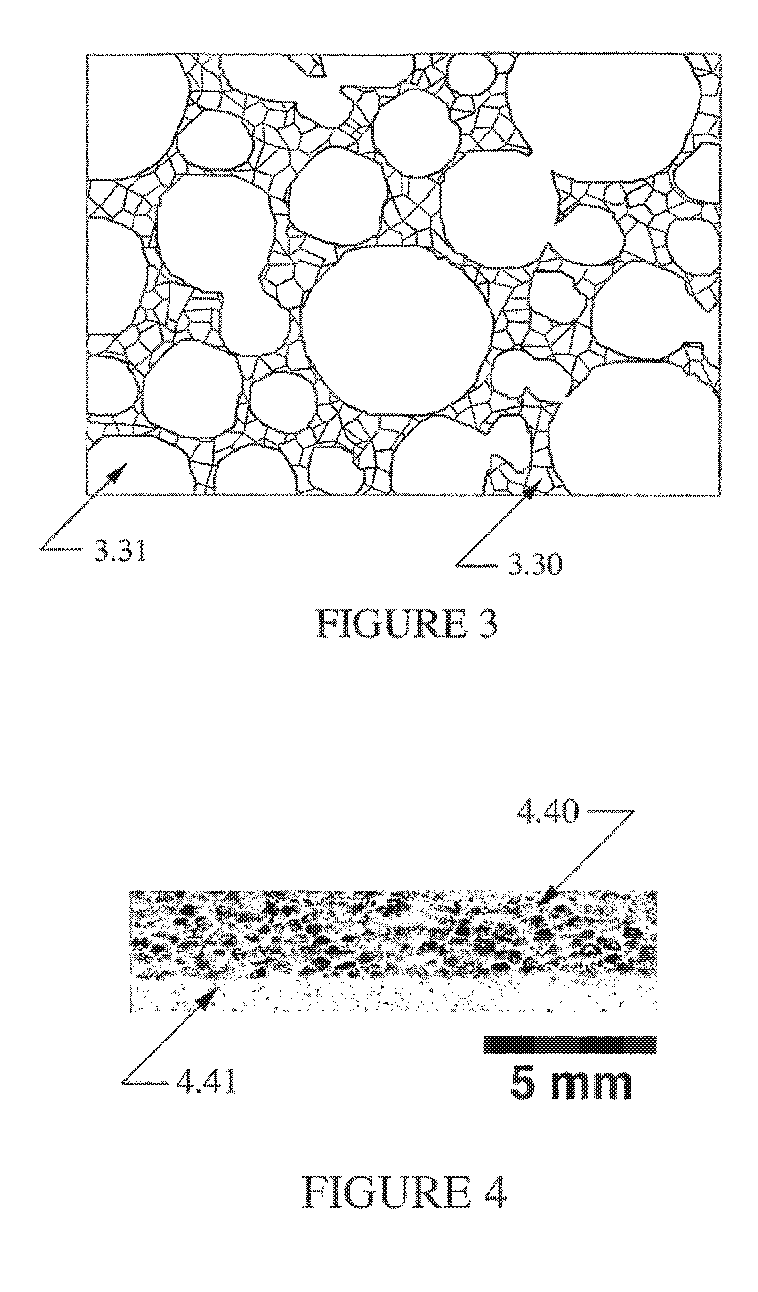
[0043]Powder metallurgy processes are used to form metal articles wherein a portion of the powder being processed is replaced with a pore forming material which is removed to form the desired porosity. The metal articles include articles that are elemental metal, metal alloys, or metal composites. The pore forming material is referred to as an extractable particulate or pore-former.
[0044]The powder and pore-former are mixed, the article is formed, optionally presintered and, thereafter, the pore-former is extracted. The powder remains to form the metal matrix of material around the pores formed by the extractable particulate. The matrix can then be further shaped and finally sintered to give the article greater strength.
[0045]The use of an extractab...
PUM
| Property | Measurement | Unit |
|---|---|---|
| porosity | aaaaa | aaaaa |
| length | aaaaa | aaaaa |
| porosity | aaaaa | aaaaa |
Abstract
Description
Claims
Application Information