Process of continuous manufacturing and installation of a thermally or electrically insulated tube or cable

a manufacturing and installation technology, applied in the field of continuous manufacturing and installation of thermally or electrically insulated tubes or cables, can solve the problems of not being particularly automated, its application onto the tube requires considerable manual intervention, etc., and achieves the effects of reducing manufacturing costs, improving thermal performance, and improving thermal performan

Active Publication Date: 2010-04-22
MAJUS +1
View PDF3 Cites 13 Cited by
  • Summary
  • Abstract
  • Description
  • Claims
  • Application Information

AI Technical Summary

Benefits of technology

[0006]The purpose of the present invention is to provide an automatic or semi-automatic installation for manufacturing of circular section elements, such as tubes or cylinders, insulated thermally or electrically, and to produce them at large lengths to achieve better control of the final product geometry, improve thermal performance in the case of insulated tubes, or electrical performance in the case of cables, reduce manufacturing costs, and eliminate a manufacturing stage, since compacting of powder takes place at the time of its direct application.
[0028]According to another process characteristic, the internal surface of the forcing device can be advantageously covered with a thickness of material facilitating gliding of the sheet on the walls of the forcing device and limiting the force required.
[0035]A first advantage of the inventive installation is reduction of manufacturing costs thanks to reduction of manual intervention.
[0037]Another advantage in case of tubes is that non-uniformities are compensated for, which results in a thermally insulated tube with better dimensional tolerances than those obtained with prior methods. The thickness of the thermally insulating element is optimized and overall global and local insulation achieved are better than those obtained with prior methods.
[0038]Another advantage is that the installation can be used quickly, at any location, and does not require qualified operators.
[0039]Another advantage is high productivity of the inventive installation and process, permitting rates of production of thermally insulated elements higher than 1 meter per minute.

Problems solved by technology

Regardless of the thermal insulator presentation, its application onto the tube requires considerable manual intervention, which to date has not been particularly automated.

Method used


Image

  • Process of continuous manufacturing and installation of a thermally or electrically insulated tube or cable
  • Process of continuous manufacturing and installation of a thermally or electrically insulated tube or cable
  • Process of continuous manufacturing and installation of a thermally or electrically insulated tube or cable

Examples


Embodiment Construction

[0045]As indicated above, the invention is meant to assure better thermal insulation performance for a given external diameter of the final object, considerable reduction of costs of installation of the insulating material, taking into account the tolerances to optimize implementation and reduce the overall costs of the system.

[0046]The following part of the description is devoted in particular to a tube to be thermally insulated, as well as any circular section element that can be insulated by the installation, such as a cable to be electrically insulated or any other element, without limiting the scope of the invention. In the following description, we discuss in particular a thermal insulator, with the understanding that in case of a cable, the insulator is an electric insulator, but does not modify the installation described below.

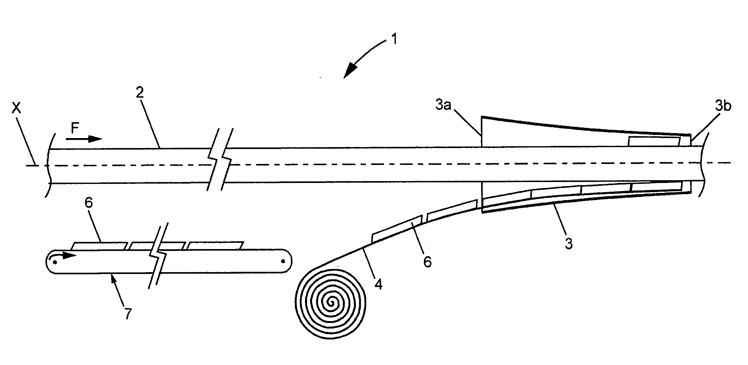
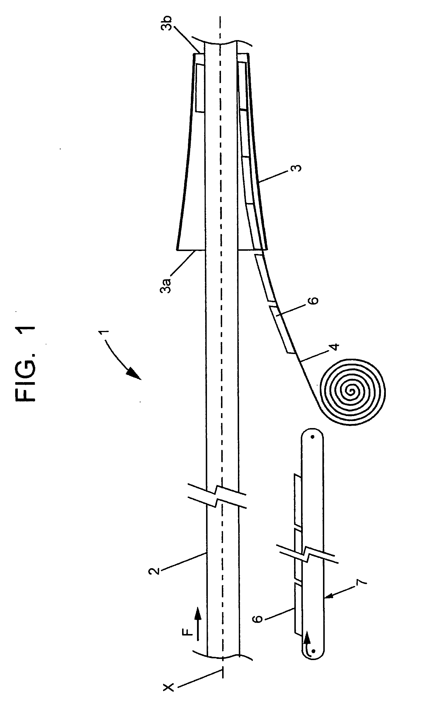
[0047]FIG. 1 is a schematic partially cross-sectional representation of installation 1 according to the invention, wherein a thermally insulating mate...


PUM

PropertyMeasurementUnit
lengthaaaaaaaaaa
lengthaaaaaaaaaa
thicknessaaaaaaaaaa

Abstract

An installation (1) for continuous application of thermally or electrically insulating material (6) around an elongate element (2) having a generally circular cross-section. The installation includes a forcing device (3), in form of a conical tube into which the element (2) is fed simultaneously at the large base end of the conical tube, a sheet (4), on which the insulating material (6) is placed, means for translation of the element through a circular section (2) of the sheet (4), and a device (7) for depositing of insulating material onto the sheet. Such an installation produces thermally insulated tubes or electrically insulated cables.

Description

CROSS REFERENCE TO RELATED APPLICATION[0001]This application claims the benefit of the prior French Patent Application No. 08-05786, filed Oct. 20, 2008, the entirety of which is hereby incorporated by reference into the present application.BACKGROUND[0002]The present invention is represented by installations permitting the manufacturing of circular cross section elements such as tubes or electrical cables insulated with an insulating material, in particular for installing insulating material around tubes or cylinders.[0003]Generally, thermal insulator material comes either in the form of half-bodies, which are applied against the tube, or which is rolled around the tube in the form of a coating. Regardless of the thermal insulator presentation, its application onto the tube requires considerable manual intervention, which to date has not been particularly automated.[0004]Thermally insulated tubes are used in various industries for transport of hot or cold liquids and to maintain th...

Claims


Application Information

Patent Timeline
Patent Type & Authority Applications(United States)
IPC IPC(8): H01B19/00F16L59/14H01B7/00
CPCB29C44/324F16L59/026F16L59/028H01B13/224Y10T29/53126Y10T29/532Y10T29/49227Y10T29/5313Y10T29/53261B29C44/3407B29C53/52B29C63/065B29C70/68B29C70/88F16L59/022F16L59/14H01B13/06H01B13/321
Inventor DAMOUR, JEAN-AURELIENMARCHAL, PHILIPPEOLLIER, PIERRERICHARD, GUILLAUME
Owner MAJUS
Why Eureka
Try Eureka